
 E-mail Alert
 RSS
RSS
| Citation: |
Zengqiang Ma, Zibin Song, Yongsheng Wang. A method for detecting the wheel rail attack angle based on laser line detection[J]. Opto-Electronic Engineering, 2017, 44(8): 818-825. doi: 10.3969/j.issn.1003-501X.2017.08.009

|
A method for detecting the wheel rail attack angle based on laser line detection
-
Abstract
Attack angle is a key index to evaluate the stability of snakelike motion in the train. Due to the complexity of the running train and the small angle of attack, it is difficult to measure the angle between the wheel and rail. This paper presents a method for attack angle detection based on the laser line and the direction of motion as collinear wheel on the rail surface. The laser line and orbital edge line were obtained by image correction, Meanshift smoothing, and Radon line detection, and then the angle was calculated in the image. Comparison between simulation data and test results shows that the method can realize the detection of attack angle and it is simple and feasible at the same time. Finally, the correction method of the detection error is given, which increases the stability of the detection method. This method may lay the foundation for the evaluation of stability and safety of train operation.-
Keywords:
- attack angle /
- snake motion /
- image detection /
- laser line
-

-
References
[1] 肖新标. 复杂环境状态下高速列车脱轨机理研究[D]. 成都: 西南交通大学, 2013. http://cdmd.cnki.com.cn/Article/CDMD-10613-1014251615.htm [2] 李呈祥. 高速列车运行横移及侧滚姿态主动控制研究[D]. 北京: 北京交通大学, 2014. http://cdmd.cnki.com.cn/Article/CDMD-10004-1014178155.htm [3] 程力.基于轮轨表达式的轮轨接触坐标计算方法[J].兰州工业学院学报, 2015, 22(2): 19-22. Chen Li. Computing method of the wheel-rail contact coordinate based on the wheel-rail expression[J]. Journal of Lanzhou Institute of Technology, 2015, 22(2): 19-22. [4] 陈建政. 轮轨作用力和接触点位置在线测量理论研究[D]. 成都: 西南交通大学, 2008. http://cdmd.cnki.com.cn/Article/CDMD-10613-2008178956.htm [5] 干锋, 戴焕云.基于空间矢量映射的新型轮轨接触点算法[J].机械工程学报, 2015, 51(10): 119-128. Gan Feng, Dai Huanyun. New wheel-rail contact point algorithm method based on the space vector mapping principle[J]. Journal of Mechanical Engineering, 2015, 51(10): 119-128. [6] 钟浩. 基于改善轮轨接触状态的重载车轮型面优化[D]. 成都: 西南交通大学, 2014. http://cdmd.cnki.com.cn/Article/CDMD-10613-1014252240.htm [7] Polach O. Influence of wheel/rail contact geometry on the behavior of a railway vehicle at stability limit[C]// Proceedings of the ENOC-2005, Eindhoven, Netherlands, 2005: 2203-2210. https://www.researchgate.net/publication/228526991_Influence_of_wheelrail_contact_geometry_on_the_behaviour_of_a_railway_vehicle_at_stability_limit [8] 庞国斌, 吴成德, 李刚, 等.机车轮轨冲角测试系统研究[J].内燃机车, 2005(12): 16-19. doi: 10.3969/j.issn.1003-1820.2005.12.004 [9] Koo J S, Choi S Y. Theoretical development of a simplified wheelset model to evaluate collision-induced derailments of rolling stock[J]. Journal of Sound and Vibration, 2012, 331(13): 3172-3198. doi: 10.1016/j.jsv.2012.02.014 [10] 马贺, 张军, 张秀娟, 等.冲角对低地板车辆轮轨接触状况的影响[J].机械工程学报, 2015, 51(24): 112-117. Ma He, Zhang Jun, Zhang Xiujuan, et al. Influence of attack angle on wheel/rail contact of low-floor vehicles[J]. Journal of Mechanical Engineering, 2015, 51(24): 112-117. [11] 李国顺, 金炜, 范荣巍.基于图像识别的轮轨冲角测量系统研究[J].中国铁道科学, 2005, 26(5): 82-85. Li Guoshun, Jin Wei, Fan Rongwei. Research on the measurement system of the attack angle between wheel and rail based on image identification[J]. China Railway Science, 2005, 26(5): 82-85. [12] 肖绯雄, 史炎.轮轨冲角测量装置的研究[J].内燃机车, 1997(2): 44-48. [13] 肖乾, 徐红霞, 成棣, 等.不同轮轨冲角下高速轮轨稳态滚动接触的蠕滑特性[J].中国铁道科学, 2014, 35(1): 60-66. Xiao Qian, Xu Hongxia, Cheng Di, et al. Creep characteristics of high-speed wheel-rail steady-state rolling contact under different attack angles[J]. China Railway Science, 2014, 35(1): 60-66. [14] 张宇. 数字图像梯形畸变校正算法研究与视频实时校正应用[D]. 合肥: 安徽大学, 2014. http://cdmd.cnki.com.cn/Article/CDMD-10357-1014229339.htm [15] 郑丽颖, 何萌萌, 刘娇.改进的广义插值傅里叶变换方法[J].应用科技, 2015, 42(3): 55-59, 64. Zheng Liying, He Mengmeng, Liu Jiao. Method for improving the generalized interpolated Fourier transform[J]. Applied Science and Technology, 2015, 42(3): 55-59, 64. [16] 蒋超, 牛宏侠.基于改进Radon变换的直线钢轨识别算法[J].铁道标准设计, 2017, 61(4): 19-22. Jiang Chao, Niu Hongxia. Linear rail recognition algorithm based on improved radon transform[J]. Railway Standard Design, 2017, 61(4): 19-22. [17] Easton R L Jr, Barrett H H. Tomographic transformations in optical signal processing[M]. New York: Academic Press, 1987: 335-386. [18] Shi Daming, Zheng Liying, Liu Jigang. Advanced Hough transform using a multilayer fractional Fourier method[J]. IEEE Transactions on Image Processing, 2010, 19(6): 1558-1566. doi: 10.1109/TIP.2010.2042102 [19] Pan Wei, Qin Kaihuai, Chen Yao. An adaptable-multilayer fractional fourier transform approach for image registration[J]. IEEE Transactions on Pattern Analysis and Machine Intelligence, 2009, 31(3): 400-413. doi: 10.1109/TPAMI.2008.83 -
Overview

In the locomotive operation, because of the hunting motion caused by pure conical tread, a lateral force and complex creep force between the wheel and rail will emerge and result in attack angle between the wheel and rail when crossing a curve line. Although the attack angle is microscopic, it affects the wheel/rail contact loss and vehicle safety seriously and attack angle is a key index to evaluate the stability of snakelike motion in the train. Monitoring and analyzing the wheel/rail contact condition and the change of attack angle in the locomotive operation play a significant role in the stability and safety of vehicle operation. Due to the complexity of the running train and the small angle of attack, it is difficult to measure the angle between the wheel and rail. A method for combining the on-board camera with the laser line is presented to complete the image acquisition and detect the attack angle based on the laser line and the direction of motion as collinear wheel on the rail surface. The laser line and orbital edge line are obtained by some algorithms such as image pre-processing algorithm, image correction, Meanshift smoothing, and Radon line detection. The angle between the laser line and orbital edge in the image can be got through a series of image processing algorithms, which can reflect the attack angle in the running of locomotive. Radon detection algorithm is used to detect the relative position between laser line and rail edge line, and different conditions of undershooting changes are compared by simulation. The comparison between simulation data and experimental data shows that the method can simply realize the detection of attack angle and it is feasible enough. The results of detection illustrate that the change of attack angle is between 0.355 and -0.72 degrees, and the maximum error is 0.091 degrees. Finally, the correction method of the detection error and measurement accuracy analysis is given, which increases the stability of the detection method and demonstrates that it can meet the demand in engineering applications. It costs about 500 ms when the system completes primary detection of attack angle, which indicates that the detection speed is fast enough, and it can meet the detection requirements in engineering applications. However, some factors such as illumination and external vibration still need to be further studied to emphasize the robustness of the system. This method lays a foundation for further monitoring the condition of train operation and improving the safety mechanism of train.
-
Access History
Figures(18)
Tables(2)
Article Metrics

Export File
Citation
Zengqiang Ma, Zibin Song, Yongsheng Wang. A method for detecting the wheel rail attack angle based on laser line detection[J]. Opto-Electronic Engineering, 2017, 44(8): 818-825. doi: 10.3969/j.issn.1003-501X.2017.08.009
Format
Content
 DownLoad:

-
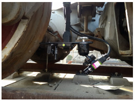
Figure 1.
The device system of detection.
-
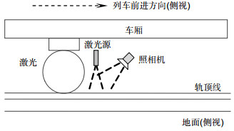
Figure 2.
The schematic diagram of system.
-
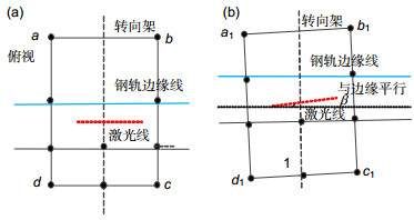
Figure 3.
Schematic diagram of the attack angle at different time. (a) Have no attack angle. (b) Have attack angle.
-
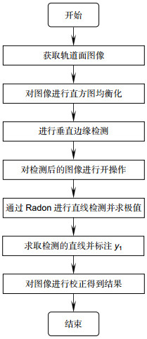
Figure 4.
Flow chart of trapezoid calibration.
-
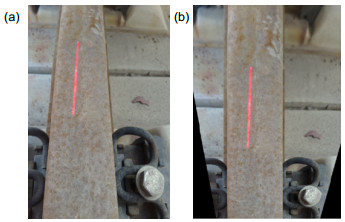
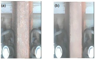
Figure 5.
Comparison before and after trapezoidal calibration. (a) Before calibration. (b) After calibration.
-
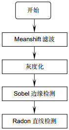
Figure 6.
The flow chart of orbital image.
-
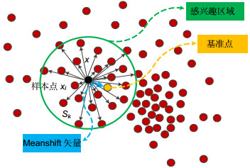
Figure 7.
Schematic diagram of Meanshift clustering algorithm.
-
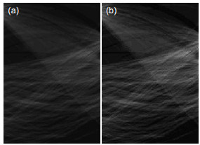
Figure 8.
The comparison before and after Meanshift. (a) Before Meanshift. (b) After Meanshift.
-
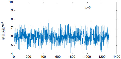
Figure 9.
Analysis of C(α1, α2) and error.
-
Figure 10.
Radon transformation under different parameters. (a) Min interpolation error. (b) Max interpolation error
-
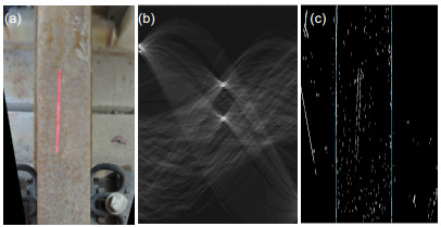
Figure 11.
Results of track edge detection. (a) Input image. (b) Radon transform. (c) The line radon.
-
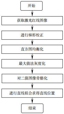
Figure 12.
Flow chart of straight line extraction.
-
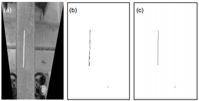
Figure 13.
Extraction results of laser line. (a) Gray images. (b) Skeleto image. (c) Fitted straight line.
-
Figure 14.
Simulation diagram of wheel rail attack angle. (a) Simulation of wheel rail attack angle of first axle. (b) Simulation of wheel rail attack angle of third axle.
-
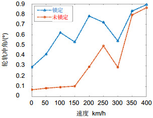
Figure 15.
Comparison of wheel / rail thrust angle in two states.
-
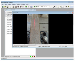
Figure 16.
System image acquisition interface.
-
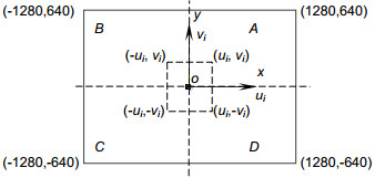
Figure 17.
Area selection of image coordinate plane.
-
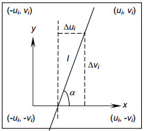
Figure 18.
Image center area.


