
 E-mail Alert
 RSS
RSS
-
摘要:
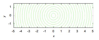
由于双光楔系统可以精确调整光轴的指向,而且具有结构简单紧凑、调整速度快、偏转角度大的优点。为了满足某产品的需要,实现同心圆和Z字型的光轴调整轨迹。本文根据现有理论,通过建立光轴偏转角度与双光楔转动角度关系模型,推导出对应公式,并结合Matlab仿真、拟合和实际的产品测试,设计出了利用ARM与计算机控制双光楔来调整光轴指向的方案。结果表明,该方案光轴指向调整的误差小于0.5°,能够实现预期的轨迹,满足实际产品的需求。
 Abstract:
Because the double-wedge system can accurately adjust the orientation of the optical axis, it has the advantages of simple and compact structure, fast adjustment speed, and large adjustment angle. In order to meet the needs of a certain product, optical axis adjustment trajectories of concentric circles and zigzags are realized. Based on the existing theories, this paper establishes the corresponding formula by establishing the relationship between the optical axis deflection angle and the bi-wedge rotation angle model, and combines the Matlab simulation, the fitting and the actual product testing, and designs the use of ARM and computer-controlled bi-optical wedges to adjust the orientation of the optical axis. The results show that the error of the optical axis pointing adjustment of the scheme is less than 0.5°, and the expected trajectory can be achieved to meet the requirements of actual products.
-

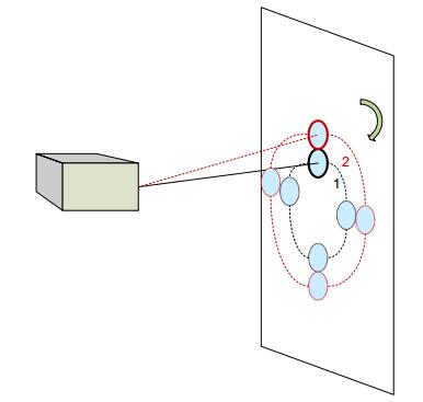
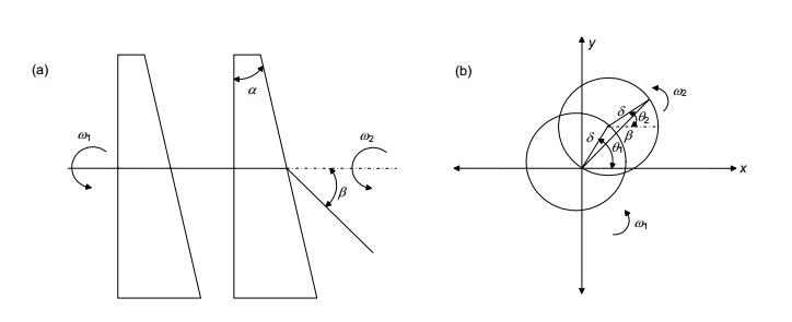
Overview: A prism with a small refraction angle is called a wedge. Double optical wedges, also known as Risley prism pairs, are opto-mechanical components that consist of two closely spaced optical wedges with the same refractive index and equal angular refraction. Its main function is to adjust the optical axis by adjusting the rotation angle of the double wedge. In addition to the dual-optical wedge, which can realize the function of a single optical wedge, the relative motion of the two optical wedges can make the equivalent refraction angle of the two optical wedges change within a range of 0 to 2 single refraction angles of the single wedge, and select different rotation speeds and directions. One can get different scan patterns. Therefore, dual-optical wedges can form a flexible and diverse scanning format, and the structure is simple and easy to use. Based on the above advantages, bi-optic wedges are widely used in navigation systems, laser radar systems, satellite interactive systems, and laser micro-hole processing optical path control, high-precision angle generator.
When the double-wedge system is generally used, the rotation speed of the optical wedge is relatively stable and the control is relatively simple, and it is possible to realize the linear and petal-type trajectories; but when more complex trajectories are required, such as concentric circles and zigzags, this simple control method obviously cannot be achieved. In order to meet the needs of a certain product, optical axis adjustment trajectories of concentric circles and zigzags are realized. Based on the existing theories, this paper establishes the relationship between the optical axis deflection angle and the bi-wedge rotation degree model, and derives the corresponding formula. In combination with Matlab simulation, fitting and actual product testing, the dual-optical wedge using ARM and computer control is designed. To adjust the orientation of the optical axis. The results show that the error of the optical axis pointing adjustment of the scheme is less than 0.5°, and the expected trajectory can be achieved to meet the requirements of actual products. And the control method of the dual optical wedge controlled by the control system composed of ARM and stepper motor is given. The significance of this paper is to propose a new scheme for the traditional bi-wedge scanning method, and to give a realization method of concentric circles and zigzag scanning. And matlab simulation and actual test and experimental data analysis were carried out on the program. Through experimental analysis, we can see that the new program can meet the requirements of specific projects with high efficiency and time saving when facing different spot sizes. Based on the existing theory, this scheme is one of practical examples of dual-wedge scanning applications and concrete engineering, and extends the application range of dual-wedge scanning.
-

-
表 1 实验结果比较
Table 1. Comparison of experiment results
理论值 实际值 楔镜1/(°) 楔镜2/(°) 楔镜1/(°) 楔镜2/(°) -18.292 43.3253 -17.795 42.936 6.2747 39.4653 6.9744 39.9533 83.627 96.373 83.103 96.294 -9.94809 -40.2737 -9.6361 -39.9837 15.9235 -42.3002 16.1011 -42.3351 25.8583 -34.3227 25.9714 -34.3882 7.40798 -23.4146 7.0691 -22.9791 87.8796 92.1204 87.4309 92.0776 -4.9906 22.7488 -5.0197 22.7611 -23.9013 32.834 -23.5569 33.2904 -34.3227 25.8583 -34.1864 25.386 -23.4146 7.40798 -23.7402 7.3112 92.1204 87.8796 91.8225 87.5117 22.7488 -4.9906 22.7468 -4.8345 32.834 -23.9013 33.172 -23.8074 43.3253 -18.292 42.9357 -17.801 39.4653 6.2747 39.9542 6.9741 96.373 83.627 96.302 83.135 -40.2737 -9.94809 -40.2735 -9.64516 -42.3002 15.9235 -42.3205 15.9179  下载: 导出CSV
-
[1] 郁道银, 谈恒英.工程光学[M]. 2版.北京:机械工业出版社, 2006.
Yu D Y, Tan H Y. Optical Engineering[M]. 2nd ed. Beijing: Mechanical Industry Press, 2006.
[2] 胡玉禧, 安连生.应用光学[M].合肥:中国科学技术大学出版社, 1996.
Hu Y X, An L S. Applied Optics[M]. Hefei: University of Science and Technology of China, 1996.
[3] 贺磊, 袁家虎, 李展, 等.双光楔高精度角度发生器设计[J].光电工程, 2002, 29(6): 46–49, 60. doi: 10.3969/j.issn.1003-501X.2002.06.013
He L, Yuan J H, Li Z, et al. Design of high-precision angle generator with double optical wedges[J]. Opto-Electronic Engineering, 2002, 29(6): 46–49, 60. doi: 10.3969/j.issn.1003-501X.2002.06.013
[4] 余巍.双光楔扫描激光雷达三维动态仿真研究[D].武汉: 华中科技大学, 2015.
Yu W. 3D dynamic simulation of dual wedge scanning LiDAR[D]. Wuhan: Huazhong University of Science and Technology, 2015.
[5] Degnan J, Machan R, Leventhal E, et al. Inflight performance of a second-generation photon-counting 3D imaging lidar[J]. Proceedings of SPIE, 2008, 6950: 695007. doi: 10.1117/12.784759
[6] 王保华.主动式激光制导导引头光学系统设计[D].长春: 中国科学院长春光学精密机械与物理研究所, 2012.
Wang B H. Optical design and stray light analysis of active laser-guided seeker[D]. Changchun: Changchun Institute of Optics, Fine Mechanics and Physics, Chinese Academy of Sciences, 2012.
http://cdmd.cnki.com.cn/Article/CDMD-80139-1013281213.htm [7] 吕溥, 韩国华.双光楔在激光测距机光轴校正中的应用[J].激光技术, 2012, 36(2): 151–153. doi: 10.3969/j.issn.1001-3806.2012.02.002
Lv P, Han G H. Application of dual wedges in optical axis alignment for laser rangefinders[J]. Laser Technology, 2012, 36(2): 151–153. doi: 10.3969/j.issn.1001-3806.2012.02.002
[8] 郭云曾, 杨小军, 杨小君, 等.旋转双光楔光路引导系统Matlab仿真研究[J].红外与激光工程, 2014, 43(3): 856–860. doi: 10.3969/j.issn.1007-2276.2014.03.034
Guo Y Z, Yang X J, Yang X J, et al. Simulation study of rotating double optical wedge vectoring optics path based on Matlab[J]. Infrared and Laser Engineering, 2014, 43(3): 856–860. doi: 10.3969/j.issn.1007-2276.2014.03.034
[9] Rosell F A. Prism scanner[J]. Journal of the Optical Society of America, 1960, 50(6): 521–526. doi: 10.1364/JOSA.50.000521
[10] 韦中超, 熊言威, 莫玮, 等.旋转双光楔折射特性与二维扫描轨迹的分析[J].应用光学, 2009, 30(6): 939–943. doi: 10.3969/j.issn.1002-2082.2009.06.011
Wei Z C, Xiong Y W, Mo W, et al. Analysis of refraction characteristics of two-wedge rotation and two-dimensional scanning trajectory[J]. Journal of Applied Optics, 2009, 30(6): 939–943. doi: 10.3969/j.issn.1002-2082.2009.06.011
[11] Shan J, Toth C K. Topographic Laser Ranging and Scanning: Principles and Processing[M]. London: Taylor & Francis Group, 2008.
-

 点击扫一扫
点击扫一扫
图(6)
表(1)
计量
- 文章访问数: 5399
- PDF下载数: 1227
- 施引文献: 0


