
 E-mail Alert
 RSS
RSS
| Citation: |
Zhang Yong, Wu Hao, Ma Sasa. Development and analysis of large spacing axis consistency detection technology[J]. Opto-Electronic Engineering, 2019, 46(2): 180409. doi: 10.12086/oee.2019.180409

|
Development and analysis of large spacing axis consistency detection technology
-
Abstract
The axis consistency of multiple optical sensors is an important guarantee to ensure the normal operation for photoelectric task equipment of weapon system. The presented status quo of methods and equipment are analyzed for measuring the consistency of large spacing axes. An axis consistency detection method is proposed based on non-cooperative target image processing technology. Specifically, it is available to select scenes with typical characteristics in the far field as non-cooperative targets. Then, the axis consistency detection results are obtained by comparing the position differences of non-cooperative targets in different image spaces. Compared with other detection methods and equipment, our method avoids many disadvantages including huge volume, heavy weight and the limited operation environment. Furthermore, it is especially suitable for axis detection of in field and on-line to large-distance photoelectric equipment, which shows a bright application prospect.-
Keywords:
- axis consistency /
- detection /
- image processing /
- multiple optical sensors /
- large spacing
-

-
References
[1] 凌军, 刘秉琦, 赵熙林.几种光轴平行性测试方法的比较与探讨[J].应用光学, 2003, 24(1): 43-45. doi: 10.3969/j.issn.1002-2082.2003.01.015 Ling J, Liu B Q, Zhao X L.The comparison and discussion of several testing methods about optical-axis parallelism[J].Journal of Applied Optics, 2003, 24(1):43-45. doi: 10.3969/j.issn.1002-2082.2003.01.015 [2] 姜宏滨.用投影靶板调整光轴平行性[J].舰船科学技术, 1995(4): 61-65. Jiang H B.adjusting optical axis parallelism with projection target plate[J].Ship Science and Technology, 1995(4):61-65. [3] 刘爱敏, 高立民, 吴易明, 等.ZEMAX辅助分析斜方棱镜面形误差对出射光平行度的影响[J].应用光学, 2009, 30(3):491-495. doi: 10.3969/j.issn.1002-2082.2009.03.028 Liu A M, Gao L M, Wu Y M, et al.ZEMAX auxiliary analysis for effect of rhombic prism surface shape error on parallelism of emergent beam[J].Journal of Applied Optics, 2009, 30(3): 491-495. doi: 10.3969/j.issn.1002-2082.2009.03.028 [4] 常山, 曹益平, 陈永权.五角棱镜的光束转向误差对波前测量的影响[J].应用光学, 2006, 27(3): 186-191. doi: 10.3969/j.issn.1002-2082.2006.03.005 Chang S, Cao Y P, Chen Y Q.Influence of beam turning error of pentagonal prism on wave-front measurement[J].Journal of Applied Optics, 2006, 27(3):186-191. doi: 10.3969/j.issn.1002-2082.2006.03.005 [5] 金伟其, 王霞, 张其扬, 等.多光轴一致性检测技术进展及其分析[J].红外与激光工程, 2010, 39(3):526-531. doi: 10.3969/j.issn.1007-2276.2010.03.031 Jin W Q, Wang X, Zhang Q Y, et al.Technical progress and its analysis in detecting of multi-axes parallelism system[J].Infrared and Laser Engineering, 2010, 39(3): 526-531. doi: 10.3969/j.issn.1007-2276.2010.03.031 [6] Yang L H, Yang X Y, Zhu J G, et al.Novel method for spatial angle measurement based on rotating planar laser beams[J].Chinese Journal of Mechanical Engineering, 2010, 23(6): 758-764. doi: 10.3901/CJME.2010.06.758 [7] 郑迎亚, 邾继贵, 薛彬, 等.室内空间测量定位系统网络布局优化[J].光电工程, 2015, 42(5):20-26. doi: 10.3969/j.issn.1003-501X.2015.05.004 Zheng Y Y, Zhu J G, Xue B, et al.Network deployment optimization of indoor workspace measurement and positioning system[J].Opto-Electronic Engineering, 2015, 42(5):20-26. doi: 10.3969/j.issn.1003-501X.2015.05.004 [8] Jaklitsch J J, Ehart A F, Jones D A, et al.Gyroscopic system for boresighting equipment: US7065888B2[P].2006-06-27. [9] Jaklitsch J J, Paturzo V M.Non line of sight boresight based on inertial measurement technology[C]//Proceedings AUTOTESTCON 2003.IEEE Systems Readiness Technology Conference, Anaheim, USA, 2003: 527-533. [10] Ahmadabadian A H, Yazdan R, Karami A, et al.Clustering and selecting vantage images in a low-cost system for 3D reconstruction of texture-less objects[J].Measurement, 2017, 99: 185-191. doi: 10.1016/j.measurement.2016.12.026 [11] 关印, 王向军, 阴雷, 等.基于物体表面形貌的单相机视觉位姿测量方法[J].光电工程, 2018, 45(1):170522. doi: 10.12086/oee.2018.170522 Guan Y, Wang X J, Yin L, et al. Monocular position and pose measurement method based on surface topography of object[J].Opto-Electronic Engineering, 2018, 45(1):170522. doi: 10.12086/oee.2018.170522 [12] Metronor.Next generation boresight system[EB/OL]. http:www.metronor.com/military/. [13] 杨博文.大型装备装配位姿视觉检测的关键技术研究[D].南京: 南京航空航天大学, 2013. Yang B W.Research on the key technologies of vision-based assambly pose measurement for large-scale equipments[D].Nanjing: Nanjing University of Aeronautics and Astronautics, 2013. http://cdmd.cnki.com.cn/Article/CDMD-10694-1015951917.htm [14] 翁璇, 叶南, 张丽艳.单目视觉测量系统中目标位姿对图像点灵敏度影响的研究[J].机械科学与技术, 2015, 34(6):969-973. Weng X, Ye N, Zhang L Y.Effects of the target position on the sensitivity of image point in monocular visual measurement system[J].Mechanical Science and Technology for Aerospace Engineering, 2015, 34(6): 969-973. [15] 胡禹, 谢天保, 廖祖平, 等.基于光电跟踪的飞机校靶技术研究[J].测控技术, 2016, 35(10):124-128. doi: 10.3969/j.issn.1000-8829.2016.10.031 Hu Y, Xie T B, Liao Z P, et al. Research on aircraft boresight based on photoelectric tracking[J].Measurement & Control Technology, 2016, 35(10):124-128. doi: 10.3969/j.issn.1000-8829.2016.10.031 [16] 黄鹏, 王青, 俞慈君, 等.飞机航炮的数字化校准分析[J].光学 精密工程, 2013, 21(12):3102-3110. Huang P, Wang Q, Yu C J, et al. Accuracy analysis for digital boresighting of aircraft gun[J].Optics and Precision Engineering, 2013, 21(12):3102-3110. [17] CI Systems.Advanced weapon optical boresight system (O-AWBS)[EB/OL].(2015-10-12)[2016-07-20].http://www.ci-systems.com/Advanced-Weapon-Boresight-System-(AWBS). [18] Cabib D, Rahav A, Barak T.Broad-band optical test bench (OPTISHOP) to measure MTF and transmittance of visible and IR optical components[J].Proceedings of SPIE, 2007, 6543: 654311. doi: 10.1117/12.719170 [19] Carl Zeiss.Calibration and alignment[EB/OL].http://www.zeiss.com/optronics. [20] Schill Reglerteknik.Aligner 308 ship alignment system[EB/OL]. http://www.schill.se. -
Overview

Overview: The axes consistency among different task modules in the platform photoelectric equipment and the axes consistency between the platform photoelectric equipment and gun barrel axis affect directly the operational effectiveness of weapon system. As a result, it is particularly urgent to carry out the research and equipment development of optical axis consistency detection technology of the platform photoelectric equipment under in field and on-line conditions. Obviously, large spacing, wide spectrum and multi-axis are the main characteristics of axis consistency detection for platform photoelectric equipment.
The presented status quo of methods and equipment are analyzed for measuring the consistency of large spacing axes. According to the above analysis, the large-spacing optical axis consistency measuring method and equipment have their own advantages and disadvantages respectively in terms of measuring range, measuring accuracy, portability and price. For example, the projection target plate measuring method is limited clearly by site and environmental conditions. Meanwhile, the collimator measuring method is used mostly in laboratory conditions. Furthermore, the cost of the inertial measuring method and the photogrammetry measuring method is high although they can meet the large-distance axis detection needs. In contrast, the intersecting target calibration method is simple in structure and portable in operation in spite of requiring a long visual distance. The applicability of axis detection equipment in field and on-line will be greatly improved if the visual distance can be shortened effectively on the premise of ensuring the measurement accuracy.
Therefore, an axis consistency detection method is proposed based on non-cooperative target image processing technology. Specifically, it is available to select scenes with typical characteristics in the far field as non-cooperative targets. Then, the axis consistency detection results are obtained by comparing the position differences of non-cooperative targets in different image spaces. The experimental results and error analysis show that the method can meet the requirements of large spacing axis consistency detection. The average value of angle measurement error is 15.96″ and the standard deviation is 2.80″ respectively for two parallel visible light axes. Meanwhile, it is available to select the visibility distance of about 100 m as the observation distance between the object to the measured target can meet the detection accuracy requirements of most photoelectric equipment. Compared with other detection methods and equipment, the method avoids many disadvantages including huge volume, heavy weight and limited operation environment. It is especially suitable for axis detection of in field and on-line to large-distance photoelectric equipment, which shows a bright application prospect.
-
Access History

Figures(13)
Tables(2)
Article Metrics


Export File
Citation
Zhang Yong, Wu Hao, Ma Sasa. Development and analysis of large spacing axis consistency detection technology[J]. Opto-Electronic Engineering, 2019, 46(2): 180409. doi: 10.12086/oee.2019.180409
Format
Content
 DownLoad:


-
Figure 1.
Projection target method. (a) Measured target; (b) Projection target
-
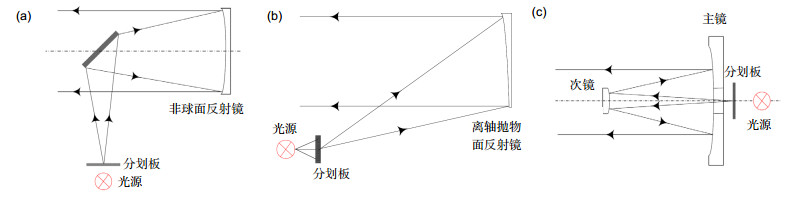
Figure 2.
Three typical optical system schematics. (a) Coaxial Newtonian system; (b) Off-axis Newtonian system; (c) Cassegrain system
-
Figure 3.
Model 310 A ABE of AAI
-
Figure 4.
HarmoLign weapon calibration system of METRONOR
-
Figure 5.
AWBS of CI
-
Figure 6.
WASVB of Carl Zeiss
-
Figure 7.
Model 308 ship axis inspection system of SCHILL
-
Figure 8.
Schematic diagram of finite distance image measurement (D is finite)
-
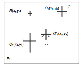
Figure 9.
Schematic diagram of image measurement
-
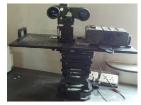
Figure 10.
Test device diagram
-
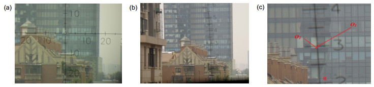
Figure 11.
Images by optical sensors capture and the diagram for center position of cross-section. (a) Images acquired by O1; (b) Images acquired by O2; (c) Schematic of enlarged images by O2
-
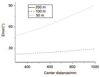
Figure 12.
Influence of different observation distances on results
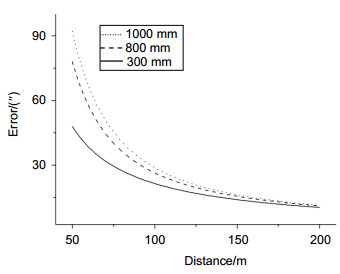
-
Figure 13.
Influence of different axis spacing on results


