
 E-mail Alert
 RSS
RSS
| Citation: |
Wang Chunmei, Huang Fengshan, Xue Ze. LiDAR measurement system and the calibration method of loading robot[J]. Opto-Electronic Engineering, 2019, 46(7): 190002. doi: 10.12086/oee.2019.190002

|
LiDAR measurement system and the calibration method of loading robot
-
Abstract
To carry out the measurement of vehicle body position and dimension of loading robot before loading, an intelligent vehicle body measurement system based on two-dimensional LiDAR was provided, and the calibration method of this system was studied as a key point. The two-dimension LiDAR was driven by rotating the platform, and the three-dimensional information of car body measured was obtained by using the single two-dimensional laser radar. In allusion to the complexity of calibration method of LiDAR measurement system and the difficulty in making calibration pieces, a system parameter calibration method was proposed based on 321 coordinate system building method, and mathematical models of calibration was established, with the principle and procedure of calibration method in detail. Measurement system was set up in a laboratory to carry out calibration experiment and measurement experiment on simulation vehicle body, and the measurement experiment for real vehicle body was conducted outside. The experiment result shows that the maximum measurement error of vehicle body size and length of this measurement system was 26.4 mm; maximum angle measurement error was 0.18 degree, which fully meets the precision requirements of loading.-
Keywords:
- vehicle body position measurement /
- LiDAR /
- loading robot /
- calibration
-

-
References
[1] 王亚军.自动装车机的结构设计和研究[D].合肥: 中国科学技术大学, 2018: 1-4. Wang Y J.Structure design and research of automatic loader[D].Hefei: University of Science and Technology of China, 2018: 1-4. [2] 谢震.粉粒料袋包装货物全自动码垛装车系统的研制[D].哈尔滨: 哈尔滨工业大学, 2016: 3-7. Xie Z.Research of automatic truck loading system for bag packaged power and granule[D].Harbin: Harbin Institute of Technology, 2016: 3-7. [3] 黄金凤, 武金艺, 肖景金, 等.水泥装车机器人结构设计与分析[J].机械设计与制造, 2016(5):136-140. doi: 10.3969/j.issn.1001-3997.2016.05.036 Huang J F, Wu J Y, Xiao J J, et al.Structure design and movement simulation of cement loading robot[J].Machinery Design & Manufacture, 2016(5):136-140. doi: 10.3969/j.issn.1001-3997.2016.05.036 [4] 黄风山, 马帅, 薛泽.旋转二维激光雷达测量系统及其标定方法[J].光电子·激光, 2018, 29(9):987-995. Huang F S, Ma S, Xue Z.A rotating two-dimensional laser radar measurement system and the calibration method[J].Journal of Optoelectronics·Laser, 2018, 29(9):987-995. [5] 韩栋斌, 徐友春, 李华, 等.基于手眼模型的三维激光雷达外参数标定[J].光电工程, 2017, 44(8):798-804. doi: 10.3969/j.issn.1003-501X.2017.08.006 Han D B, Xu Y C, Li H, et al.Calibration of extrinsic parameters for three-dimensional lidar based on hand-eye model[J].Opto-Electronic Engineering, 2017, 44(8):798-804. doi: 10.3969/j.issn.1003-501X.2017.08.006 [6] 贺俊吉, 史立.散货自动装船检测系统[J].光电工程, 2009, 36(6):52-56, 119. doi: 10.3969/j.issn.1003-501X.2009.06.011 He J J, Shi L.Inspecting system for auto-loading of bulk cargo[J].Opto-Electronic Engineering, 2009, 36(6):52-56, 119. doi: 10.3969/j.issn.1003-501X.2009.06.011 [7] 陈贵宾, 高振海, 何磊.车载三维激光雷达外参数的分步自动标定算法[J].中国激光, 2017, 44(10):249-255. Chen G B, Gao Z H, He L.Step-by-step automatic calibration algorithm for exterior parameters of 3D lidar mounted on vehicle[J].Chinese Journal of Lasers, 2017, 44(10):249-255. [8] 杨兴雨, 苏金善, 王元庆, 等.大视场线阵推扫激光3D成像雷达光束整形[J].光电工程, 2016, 43(4):89-94. doi: 10.3969/j.issn.1003-501X.2016.04.015 Yang X Y, Su J S, Wang Y Q, et al.Lined push-room laser 3D imaging radar with large field beam shaping[J].Opto-Electronic Engineering, 2016, 43(4):89-94. doi: 10.3969/j.issn.1003-501X.2016.04.015 [9] 马帅.袋装物料智能装车系统关键技术研究[D].石家庄: 河北科技大学, 2018: 5-7. Ma S.Study on key technology of intelligent loading system for bagged materials[D].Shijiazhuang: Hebei University of Science & Technology, 2018: 5-7. [10] 项志宇.快速三维扫描激光雷达的设计及其系统标定[J].浙江大学学报(工学版), 2006, 40(12):2130-2133. doi: 10.3785/j.issn.1008-973X.2006.12.024 Xiang Z Y.Fast 3D scanning laser radar system design and calibration[J].Journal of Zhejiang University(Engineering Science), 2006, 40(12):2130-2133. doi: 10.3785/j.issn.1008-973X.2006.12.024 [11] 彭梦, 蔡自兴.一种基于双平行平面的激光雷达和摄像机标定方法[J].中南大学学报(自然科学版), 2012, 43(12):4735-4742. Peng M, Cai Z X.A practical method for calibration of laser radar and camera based on double parallel planes[J].Journal of Central South University (Science and Technology), 2012, 43(12):4735-4742. [12] 石路.三维激光测量系统标定方法的理论与实验研究[D].上海: 上海交通大学, 2010: 22-34. Shi L.Theoretical and experiment research on the calibration method of 3D laser scanning system[D].Shanghai: Shanghai Jiao Tong University, 2010: 22-34. [13] 俞奇奇, 崔振山.一种基于2D激光雷达的扫描系统标定方法[J].激光与红外, 2017, 47(10):1234-1237. doi: 10.3969/j.issn.1001-5078.2017.10.008 Yu Q Q, Cui Z S.Calibration of scanning system based on 2D laser radar[J].Laser & Infrared, 2017, 47(10):1234-1237. doi: 10.3969/j.issn.1001-5078.2017.10.008 -
Overview

Overview: At present, the material loading in China is basically in semi-automatic phase. The loading work is mainly completed by manpower and trolley, fork lift truck and telescopic belt conveyor, which is with low loading efficiency, large labor intensity. The industry crying needs intelligent loading robot to achieve the intelligent loading of the materials, while the vehicle shape and bucket size of the vehicle to be loaded should be firstly determined to achieve intelligent loading. Therefore, this paper established an intelligent vehicle body measurement system based on two-dimensional LiDAR, a system parameter calibration method was proposed based on 321 coordinate system building method, and mathematical models of calibration was established, giving the principle and procedure of calibration method in detail. The result shows that the maximum measurement error of vehicle body size and length of this measurement system was 26.4 mm; maximum angle measurement error was 0.18°, which fully meets the precision requirements of loading.
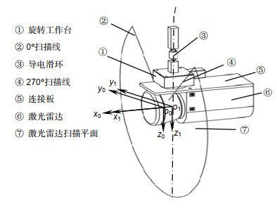
The specific calibration steps are: 1) establish LiDAR coordinate system, rotation center coordinate system, and robot loading coordinate system. The origin of LiDAR coordinate system o0 is located at the optical center of LiDAR.y0o0z0 plane is the scanning plane of LiDAR, axis o0y0 corresponds to the 45° line scan direction of LiDAR, axis o0x0 points in the dead ahead of LiDAR in front. The intersection o1 of rotation axis l of rotating platform and plane x0o0y0 is the origin of rotation center coordinate system. Three coordinate axes of rotation center coordinate system are parallel to the three axes of radar coordinate system. Loading coordinate system o2-x2y2z2 is located in the right front of the vehicle under test; 2) obtain the conversion relation between LiDAR coordinate system and rotation center coordinate system according to the installation location relationship of LiDAR and rotating platform; 3) assume that the coordinate-transformation matrix of rotation center coordinate system and loading coordinate system is T. Then calculate matrix T by substituting in special point coordinates from which we could transfer the calibration problem to looking for special point; 4) suspend a calibration board (about 2 m×2 m) over the axis o2x2 and axis o2y2 of loading coordinate system to ensure that the calibration plate is suspended directly above the axis; 5) scan the calibration plane and its adjacent ground, and two calibration plates and flat area are used as three calibration planes, then fit three plane equations, establish the coordinate system by means of 321 method and obtain the coordinates of four special points, and then solve the Tmatrix. Finally, the calibration of vehicle body measurement system is completed.
-
Access History
Figures(8)
Tables(3)
Article Metrics


Export File
Citation
Wang Chunmei, Huang Fengshan, Xue Ze. LiDAR measurement system and the calibration method of loading robot[J]. Opto-Electronic Engineering, 2019, 46(7): 190002. doi: 10.12086/oee.2019.190002
Format
Content
 DownLoad:


-
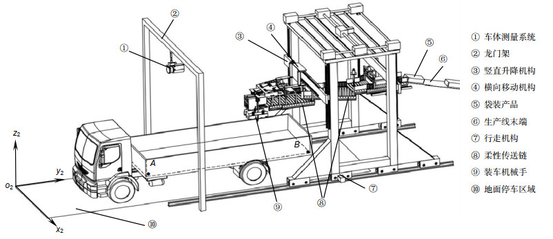
Figure 1.
Schematic diagram of the overall structure of the intelligent loading robot system
-
Figure 2.
Body measurement system
-
Figure 3.
Coordinate transformation relationship model
-
Figure 4.
Calibration plate placement position
-
Figure 5.
Scan three calibration plates
-
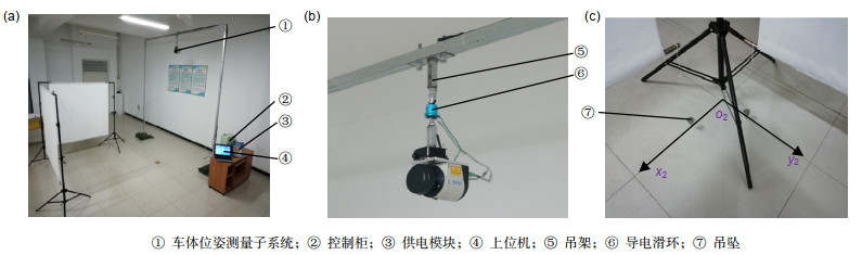
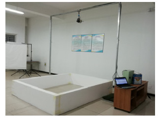
Figure 6.
Build a measurement and calibration system in the laboratory
-
Figure 7.
Measuring the simulated body
-
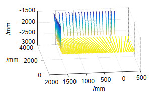
Figure 8.
Point cloud image measured on the body


