
 E-mail Alert
 RSS
RSS
| Citation: |

|
A calibration method for Lyot filter
-
Abstract
Lyot filter is widely used in solar observation for spectra-scanning imaging. Calibration experiment at regular intervals is an important work to assure the accuracy and validity of Lyot filter. This paper comes up with a new method to conduct the Lyot filter calibration experiment on-line while traditional method requires perfect stability of environment. This method uses monochromatic imaging channel and Lyot filter scanning imaging channel simultaneously, and corrects the scanning data with monochromatic imaging data to correct the impact of environment. The instability of light source caused by disturbance of observation environment is reduced. We apply the calibration method in the high-resolution multi-wavelength solar imaging system to calibrate the Lyot filter in Hɑ (656.28) scanning imaging channel and correct the scanning data with TiO band (705 nm) observation data. The result shows that this method successfully eliminate the impact of the light instability on scanning curve of Lyot filter. The difference between the ideal center and the true center of the filter is more than 0.005 nm. The accuracy of the calibration experiment and the adaptability to environment are promoted. -

-
References
[1] Goode P R, Denker C J, Didkovsky L I, et al. 1.6 M Solar telescope in big bear-the NST[J]. Journal of the Korean Astronomical Society, 2003, 36(spc1): 125–133. doi: 10.5303/JKAS.2003.36.spc1.125 [2] Ichimoto K, Ishii T T, Otsuji K, et al. A new solar imaging system for observing high-speed eruptions: Solar Dynamics Doppler Imager (SDDI)[J]. Solar Physics, 2017, 292(4): 63. doi: 10.1007/s11207-017-1082-7 [3] Bethge C, Peter H, Kentischer T J, et al. The chromospheric telescope[J]. Astronomy & Astrophysics, 2011, 534: A105. [4] Yan X L, Xue Z K, Xiang Y Y, et al. Fine-scale structures and material flows of quiescent filaments observed by the New Vacuum Solar Telescope[J]. Research in Astronomy and Astrophysics, 2015, 15(10): 1725–1734. doi: 10.1088/1674-4527/15/10/009 [5] 张鹏斌, 毛伟军.空间双折射干涉滤光器的主动补偿研究[J].应用光学, 2011, 32(6): 1093–1097. Zhang P B, Mao W J. Active compensation research of spatial birefringent filter[J]. Journal of Applied Optics, 2011, 32(6): 1093–1097. [6] 艾国祥.双折射滤光器及其在天文学中的应用[J].天文学进展, 1987, 5(4): 317–329. Ai G X. Biref ringent filter and its application to astronomy[J]. Progress in Astronomy, 1987, 5(4): 317–329. [7] 玄伟佳, 王东光, 邓元勇, 等.双折射滤光器的误差分析与性能优化[J].光学精密工程, 2010, 18(1): 52–59. Xuan W J, Wang D G, Deng Y Y, et al. Error analysis and performance optimization of birefringent filter[J]. Optics and Precision Engineering, 2010, 18(1): 52–59. [8] 曹星烨.基于液晶可调谐的宽光谱窄带Lyot型滤光片[D].杭州: 浙江大学, 2008: 12–15. Cao X Y. LC-based tunable Lyot narrow-band filter work in wide spectrum range[D]. Hangzhou: Zhejiang University, 2008: 12–15. http://cdmd.cnki.com.cn/Article/CDMD-10335-2008084188.htm [9] 徐稚, 杨磊, 向永源, 等.抚仙湖一米红外太阳望远镜Hα窄带滤光器扫描轮廓的检测与修正[J].天文研究与技术, 2014, 11(3): 239–246. Xu Z, Yang L, Xiang Y Y, et al. An investigation of spectral-line profiles from the wavelength-scanning with a narrow-band Hɑ Lyot filter on the YNAO new vacuum solar telescope[J]. Astronomical Research and Technology, 2014, 11(3): 239–246. [10] Mudge J, Tarbell T. In situ calibration of tunable filters: lyot and michelson[J]. Applied Optics, 2014, 53(22): 4978–4986. doi: 10.1364/AO.53.004978 [11] Couvidat S, Rajaguru S P, Wachter R, et al. Line-of-sight observables algorithms for the helioseismic and magnetic imager (hmi) instrument tested with interferometric bidimensional spectrometer (IBIS) observations[J]. Solar Physics, 2012, 278: 217–240. doi: 10.1007/s11207-011-9927-y [12] Rimmele T R, Hubbard R P, Balasubramaniam K S, et al. Instrumentation for the advanced technology solar telescope[J]. Proceedings of SPIE, 2004, 5492: 944–957. doi: 10.1117/12.551853 [13] Rao C H, Zhu L, Gu N T, et al. A high-resolution multi-wavelength simultaneous imaging system with solar adaptive optics[J]. The Astronomical Journal, 2017, 154(4): 143. doi: 10.3847/1538-3881/aa84b4 [14] 林元章.太阳物理导论[M].北京:科学出版社, 2000: 249–390. Lin Y Z. Introduction to Solar Physics[M]. Beijing: Science Press, 2000: 249–390. [15] 邹照伟, 程学武, 杨勇, 等.双透射峰钠原子滤光器在太阳速度场观测中的应用[J].光学学报, 2012, 32(5): 0523002. Zou Z W, Cheng X W, Yang Y, et al. Application of dual-peak-transmission sodium FADOF in solar velocity field observation[J]. Acta Optica Sinica, 2012, 32(5): 0523002. -
Overview

Overview: Lyot filter is widely used in solar observation for spectra-scanning imaging such as GST in America, SMART in Japan, ChroTel in Germany and NVST in China. As the instability caused by environment or mechanical error when the filter works, calibration experiment at regular intervals is an important work to assure the accuracy and validity of Lyot filter. Traditional method to calibrate the Lyot filter often requires the high quality of the observation weather, which makes the calibration experiment more difficult and wastes the valuable time of telescope observation time. To cover the shortage of traditional method, this paper comes up with a new method to conduct the Lyot filter calibration experiment on-line. This method uses monochromatic imaging channel and Lyot filter scanning imaging channel simultaneously. We assume that the vibration of the intensity of the monochromatic imaging is only caused by the disturbance of the observation environment. We can correct the spectra-scanning data with monochromatic imaging data to correct the impact of environment.
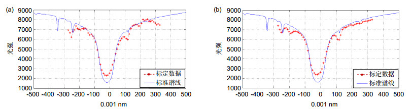
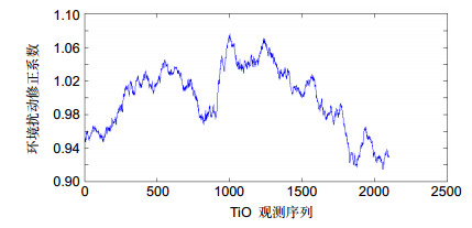
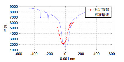
We apply the calibration method in the high-resolution multi-wavelength solar imaging system to calibrate the Lyot filter in Hɑ(656.28) scanning imaging channel and correct the scanning data with TiO band(705 nm) observation data. We calculate the correction coefficient with TiO band data, and use it to correct the spectra line pictured by Hɑ scanning imaging data. The result of line curve calibration experiment shows that this method successfully eliminate the impact of the light instability on scanning curve of Lyot filter, as the RMS of scanning curve and standard line is reduced from 482 to 456 and the shape of the scanning curve is closer to the standard line. Then we get a group of data to test the center wavelength of the spectra curve. As the result shows, the true center wavelength has a bias which is about 0.025 nm after the spectra scanning data is corrected by the TiO imaging data. According to the user guide, we change the work temperature of the filter. The center calibration experiment shows, after correcting the center wavelength by setting the work temperature of Lyot filter from 41.805 ℃ to 42.43 ℃, the difference between the idea center and the true center of the filter is reduced form about 0.025 nm to less than 0.005 nm. The center wavelength is well corrected after the calibration experiment.
As the result shows, the instability of light source caused by disturbance of observation environment is reduced and the efficiency of the calibration experiment is increased.
-
Access History
Figures(11)
Tables(3)
Article Metrics

Export File
Citation
Format
Content
 DownLoad:


-
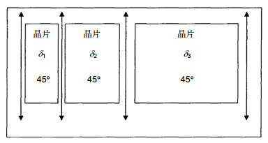
Figure 1.
The principle structure of Lyot filter
-
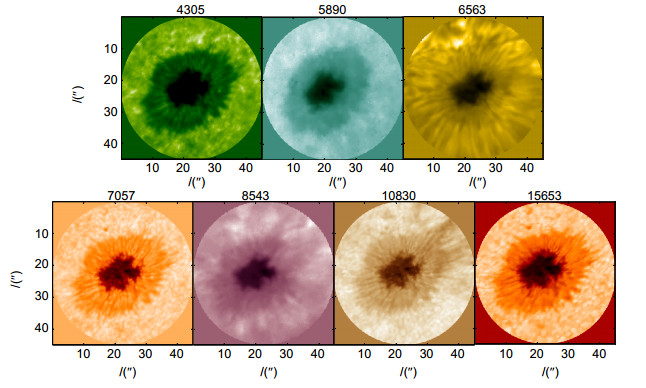
Figure 2.
Visible light to near-infrared image of different solar atmosphere layer observed by high-resolution multi-wavelength solar imaging system
-
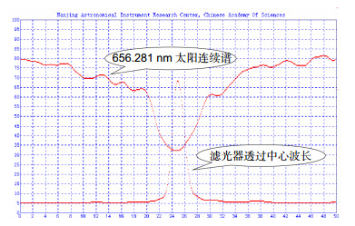
Figure 3.
Transmittance curve of the Lyot filter
-
Figure 4.
Calibration method process
-
Figure 5.
(a) Calibration data before correction; (b) Calibration data after correction
-
Figure 6.
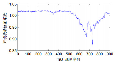
Correcting coefficient
-
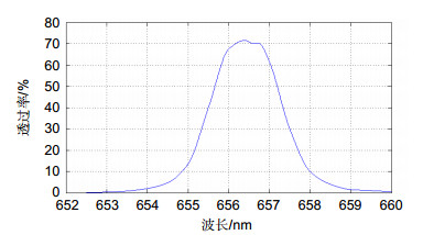
Figure 7.
Pre-filter transmittance curve
-
Figure 8.
Scanning observation line
-
Figure 9.
Correcting coefficient
-
Figure 10.
Calibration data after correction
-
Figure 11.
(a) Calibration data before correction; (b) Calibration data after correction


