
 E-mail Alert
 RSS
RSS
-
Abstract:
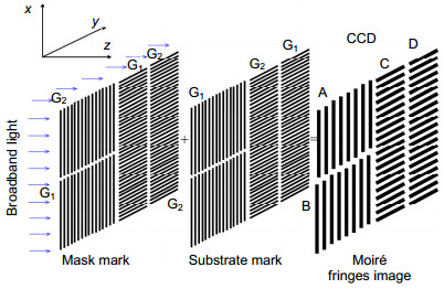
In this paper, we demonstrate an auto accurate alignment method to align mask-substrate in the prototype of plasmonic lithography (PL), which is essential for multilayer nanostructure fabrication with high resolution, low cost, high efficiency, and high throughput, such as circuit manufacturing and other applications. We obtained an alignment signal with sensitivity better than 20 nm by using the Moiré fringe image. However, only using the Moiré fringes cannot guarantee the alignment of the mask and the substrate because the Moiré fringe repeats itself when the mask and substrate are offset by a fixed displacement. To eliminate the ambiguity, boxes and the crosses alignment marks are designed beside the grating marks on the substrate and the mask, respectively. A two-step alignment scheme including coarse alignment and fine alignment is explored in the auto alignment system. In the stage of coarse alignment, the edge detection algorithm based on Canny operator is adopted to detect the edges image effectively. In the process of fine alignment, Fourier transform based on Moiré fringe image is obtained to improve the alignment accuracy. In addition, experimental results of overlay indicate that PL can obtain sub-100 nm alignment accuracy over an area of 1 cm2 using the proposed two-step alignment scheme. Via the substrate-mask mismatch compensation, better stages and precise environment control, it is expected that much higher overlay accuracy is feasible.

-
Key words:
- Moiré fringe /
- surface plasmonic lithography /
- alignment
-

Abstract: In this paper, we demonstrate an auto accurate alignment method to align mask-substrate in the prototype of plasmonic lithography (PL), which is essential to multilayer nanostructure fabrication with high resolution, low cost, high efficiency and high throughput, such as circuit manufacturing and other multilayer applications. We obtain an alignment signal with sensitivity better than 20 nm by using the Moiré fringe image that is generated by overlaying two gratings with close periods. According to the diffract theory, Moiré fringe is independent of the illumination light wavelength and the length of the gap between the mask and the substrate, which makes it very suitable for the prototype of PL. However, only the alignment of Moiré fringes cannot guarantee the alignment of the mask and the substrate because the Moiré fringe repeats itself when the mask and substrate are offset by a fixed displacement. To eliminate the ambiguity, boxes and crosses alignment marks are designed beside the grating marks on the substrate and the mask, respectively. A two-step alignment scheme including coarse alignment and fine alignment is explored in the auto alignment system. In the stage of coarse alignment, the edge detection algorithm based on Canny operator is adopted to detect the edges' image effectively and the alignment module calculates alignment deviation and controls sample stage to move until deviation is less than the expected deviation, guaranteeing the misalignment across substrate and mask within the measurement range of fine alignment. In the process of fine alignment, Fourier transform based on Moiré fringe image is obtained to calculate alignment deviation, and the auto alignment module use alignment deviation as feedback signal to align the mask and substrate. In this paper, we start, in Section 2, with the fundamental principle of Moiré fringe and its significant advantages. In Section 3 we introduce the structure and operation of the alignment system. We also demonstrate the fabrication procedures for the substrate and the auto alignment operation of PL in Section 4. In order to verify the feasibility of the proposed alignment method above, an overlay experiment is performed in Section 5. The experimental results of overlay indicate that PL can obtain sub-100 nm alignment accuracy over an area of 1 inch by using the proposed two-step alignment scheme. Furthermore, the auto alignment system and its process are also fully scalable for 4 inch or larger substrate processing. Via the substrate-mask mismatch compensation, better stages and precise environment control, it is expected that much higher overlay accuracy is feasible in the prototype of PL.
-

-

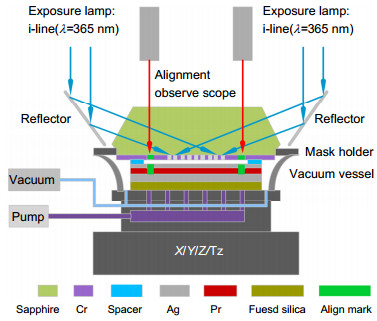
Figure 3. (a) Schematic of alignment system in PL prototype. (b) The alignment marks of the mask. (c) The alignment marks of the substrate. (d) The alignment mark layouts on the mask. (e) The alignment mark layouts on the substrate.
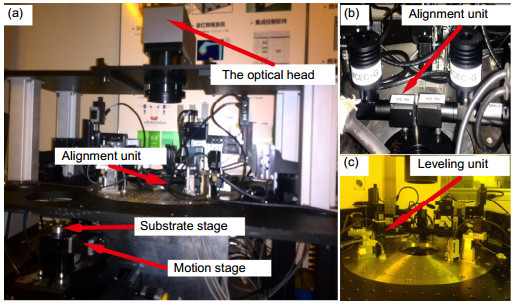
Figure 4. Photograph of (a) whole system of our prototype, (b) the alignment unit and (c) the leveling unit.
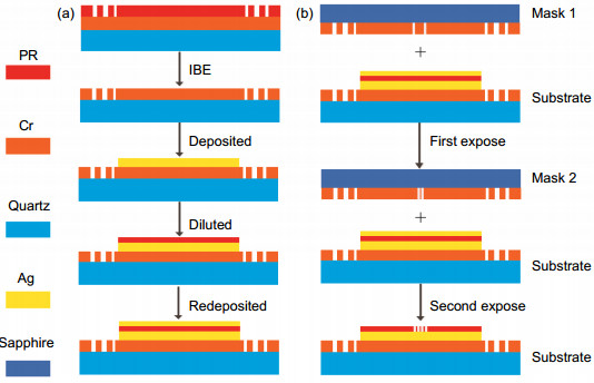
Figure 5. (a) The schematic diagram of the fabrication of substrate. (b) The schematic diagram of the overlay experiment of PL.
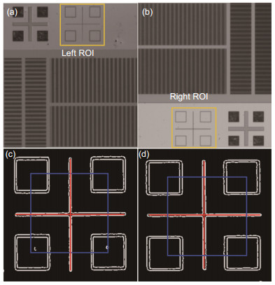
Figure 6. (a) Optical image of alignment marks in the left alignment field. (b) Optical image of alignment marks in the right alignment field. (c) The coarse alignment mark image of left alignment field. (d) The coarse alignment mark image of right alignment field.

Figure 7. (a) Spatial phase as a function of x location of left alignment field. (b) Spatial phase as a function of y location of left alignment field. (c) Spatial phase as a function of x location of right alignment field. (d) Spatial phase as a function of y location of right alignment field.
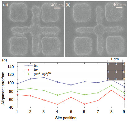
Figure 8. (a) SEM image of two sets of overlay marks in the first site position (four boxes for the first mask and a cross for the second mask). (b) SEM image of two sets of overlay marks in the last site position. (c) Statistics of misalignment with 9 measurement sites on 1 cm2 on 1 in substrate.
-
[1] Pendry J B. Negative refraction makes a perfect lens[J]. Physical Review Letters, 2000, 85(18): 3966-3969. doi: 10.1103/PhysRevLett.85.3966
[2] Luo Xiangang, Ishihara T. Surface plasmon resonant interference nanolithography technique[J]. Applied Physics Letters, 2004, 84(23): 4780-4782. doi: 10.1063/1.1760221
[3] Fang Nicholas, Lee Hyesog, Sun Cheng, et al. Sub-diffraction- limited optical imaging with a silver superlens[J]. Science, 2005, 308: 534-537. doi: 10.1126/science.1108759
[4] Holzwarth C W, Foulkes J E, Blaikie R J. Increased process latitude in absorbance-modulated lithography via a plasmonic reflector[J]. Optics Express, 2011, 19(18): 17790-17798. doi: 10.1364/OE.19.017790
[5] Luo Jun, Zeng Bo, Wang Changtao, et al. Fabrication of anisotropically arrayed nano-slots metasurfaces using reflective plasmonic lithography[J]. Nanoscale, 2015, 7: 18805- 18812. doi: 10.1039/C5NR05153C
[6] Zhao Zeyu, Luo Yunfei, Zhang Wei, et al. Going far beyond the near-field diffraction limit via plasmonic cavity lens with high spatial frequency spectrum off-axis illumination[J]. Scientific Reports, 2015, 5: 15320. doi: 10.1038/srep15320
[7] Liu Minggang, Zhao Chengwei, Luo Yunfei, et al. Subdiffraction plasmonic lens lithography prototype in stepper mode[J]. Journal of Vacuum Science & Technology B, 2017, 35(1): 011603-011611. https://www.researchgate.net/publication/312013790_Subdiffraction_plasmonic_lens_lithography_prototype_in_stepper_mode
[8] Chen Wangfu, Yan Wei, Hu Song, et al. Extended dual-grating alignment method for optical projection lithography[J]. Applied Optics, 2010, 49(4): 708-721. doi: 10.1364/AO.49.000708
[9] Li N, Wu W, Chou S Y. Sub-20-nm alginemnt in nanoimprint lithography using morie fringes[J]. Nano Letters, 2006, 6(11): 2626-2629. doi: 10.1021/nl0603395
[10] Nishi K. Method of aligning a substrate: US Patent, 5, 682. 243 [P]. 1997.
[11] Kinoshita H, Une A, lki M. A dual grating alignment technique for X-ray lithography[J]. Journal of Vacuum Science & Technology B, 1983, 1(4): 1276-1279. https://www.researchgate.net/publication/224461894_A_dual_grating_alignment_technique_for_x-ray_lithography
[12] Di Chengliang, Zhu Jiangping, Yan Wei, et al. A modified alignment method based on four-quadrant-grating Moiré for proximity lithography[J]. OPTIK, 2014, 124(17): 4868-4872. https://www.sciencedirect.com/science/article/pii/S0030402614004872
[13] Goodman J W. Introduction to fourier optics, second edition [J]. Optical Engineering, 1996, 35(5): 1513-1518. http://cn.bing.com/academic/profile?id=c6353c3ade3014b2128cfac01811a2ef&encoded=0&v=paper_preview&mkt=zh-cn
[14] Bryngdahl. Moire: Formation and interpretation[J]. Journal of the Optical Society of America, 1974, 64(10): 1287-1294. doi: 10.1364/JOSA.64.001287
-
 下载:
下载:
 点击扫一扫
点击扫一扫
图(8)
计量
- 文章访问数: 7998
- PDF下载数: 2901
- 施引文献: 0


