
 E-mail Alert
 RSS
RSS
| Citation: |
Dongbin Han, Youchun Xu, Hua Li, et al. Calibration of extrinsic parameters for three-dimensional lidar based on hand-eye model[J]. Opto-Electronic Engineering, 2017, 44(8): 798-804. doi: 10.3969/j.issn.1003-501X.2017.08.006

|
Calibration of extrinsic parameters for three-dimensional lidar based on hand-eye model
-
Abstract
It is necessary to calibrate the relative pose between the three-dimensional (3D) lidar and the GPS / INS integrated navigation system for their combination. Because of the phenomenon of point cloud distortion in vehicle moving process, a method of coordinate correction for laser scanning point in single frame point cloud is proposed. Aiming at the calibration problem, a method of extrinsic parameter calibration is proposed, based on ICP algorithm, hand-eye calibration model, and least squares method. Monte Carlo simulation results show that the algorithm is accurate and effective. The calibration experiment is carried out on the unmanned vehicle laboratory JJUV-6, and the 3D relative pose relations are obtained. It shows that after calibration the effect of 3D point clouds reconstruction is better, and the overlapping degree of point clouds is close to the registration effect. For the purpose of applications, it can meet the needs of 2D map construction and 3D environment reconstruction. -

-
References
[1] 程金龙, 冯莹, 曹毓, 等.车载激光雷达外参数的标定方法[J].光电工程, 2013, 40(12): 89-94. doi: 10.3969/j.issn.1003-501X.2013.12.015 Cheng Jinlong, Feng Ying, Cao Yu, et al. Extrinsic calibration method for multiple lidars mounted on mobile vehicle[J]. Opto-Electronic Engineering, 2013, 40(12): 89-94. doi: 10.3969/j.issn.1003-501X.2013.12.015 [2] Zhu Z, Liu J. Unsupervised extrinsic parameters calibration for multi-beam LIDARs[C]// Proceedings of the 2nd International Conference on Computer Science and Electronics, Paris: Atlantis Press, 2013. https://www.researchgate.net/publication/266646837_Unsupervised_Extrinsic_Parameters_Calibration_for_Multi-beam_LIDARs [3] Underwood J, Hill A, Scheding S. Calibration of range sensor pose on mobile platforms[C]// Proceedings Proceeding of IEEE/RSJ International Conference on Intelligent Robots and Systems, 2007: 3866-3871. https://www.researchgate.net/publication/4297043_Calibration_of_range_sensor_pose_on_mobile_platforms [4] Levinson J, Thrun S. Unsupervised calibration for multi-beam lasers[M]// Khatib O, Kumar V, Sukhatme G. Experimental Robotics. Springer Tracts in Advanced Robotics, Berlin: Springer Press, 2014, 79: 179-193. [5] Nouira H, Deschaud J E, Goulette F. Target-free extrinsic calibration of a mobile multi-beam LIDAR system[J]. ISPRS Annals of Photogrammetry, Remote Sensing and Spatial Information Sciences, 2015, Ⅱ-3/W5: 97-104. [6] User's manual and programming guide. HDL-64E S3: High definition LiDAR sensor[EB/OL]. [2017-05-20]. http://velodynelidar.com/docs/manuals/63-HDL64ES3%20REV%20J%20MANUAL,USERS%20AND%20PROGRAM%20GUIDE,HDL-64E%20S3.pdf [7] 谢德胜, 徐友春, 万剑, 等.基于RTK-GPS的轮式移动机器人轨迹跟随控制[J].机器人, 2017, 39(2): 221-229. Xie Desheng, Xu Youchun, Wan Jian, et al. Trajectory tracking control of wheeled mobile robots based on RTK-GPS[J]. Robot, 2017, 39(2): 221-229. [8] Karney C F F. Geodesics on an ellipsoid of revolution[C/OL]. Washington, USA: SRI International, [2016-12-28]. https://geographiclib.sourceforge.io/geod.html. https://www.researchgate.net/publication/48202668_Geodesics_on_an_ellipsoid_of_revolution [9] 刘江, 张旭, 朱继文.一种基于K-D树优化的ICP三维点云配准方法[J].测绘工程, 2016, 25(6): 15-18. Liu Jiang, Zhang Xu, Zhu Jiwen. ICP three-dimensional point cloud registration based on K-D tree optimization[J]. Engineering of Surveying and Mapping, 2016, 25(6): 15-18. [10] 刘佳君, 孙振国, 张文增, 等.基于平面约束的欠驱动爬壁机器人手眼标定方法[J].机器人, 2015, 37(3): 271-276, 285. Liu Jiajun, Sun Zhenguo, Zhang Wenzeng, et al. Plane-constraint based hand-eye calibration method for underactuated wall-climbing robot[J]. Robot, 2015, 37(3): 271-276, 285. [11] Tsai R Y, Lenz R K. A new technique for fully autonomous and efficient 3D robotics hand/eye calibration[J]. IEEE Transactions on Robotics and Automation, 1989, 5(3): 345-358. doi: 10.1109/70.34770 -
Overview

Based on the requirement of high precision map construction for unmanned vehicle, the relative pose calibration between three-dimensional lidar and GPS/INS integrated navigation system is necessary. The coordinate systems of the three-dimensional lidar and the GPS/INS integrated navigation system are established according to the characteristics of each type, respectively. Aiming at the problem that the relative position between the two coordinate systems can not be measured accurately and the relative rotation angles between them are difficult to be measured, the calibration of three-dimensional (3D) lidar external parameters is studied. Based on the point cloud registration, the hand-eye calibration model of 3D lidar and GPS/INS integrated navigation system is established. The point cloud pose is obtained after registration by ICP algorithm. Using the multi-pairs point cloud pose, the extrinsic parameters are calculated by the least square method.
The 3D lidar data are resolved into continuous single frame point clouds, and the longitude and latitude coordinates of GPS are converted into plane coordinates. At the same time, the data of the two kinds of sensors are synchronized in time, and the pose tag is attached to each point cloud frame. Aiming at the phenomenon of point cloud distortion in vehicle moving process, a method of coordinate correction for laser scanning point in single frame point cloud is proposed. The point cloud with the attitude angle changed is chosen as the point cloud pair. A point cloud registration algorithm is used to register the corresponding point cloud pairs, and the new pose after registration is obtained. The relative pose of each pair of cloud points before and after registration can satisfy the model of hand-eye calibration. Finally, a set of over determined equations is constructed by multi-pairs registration data satisfying the “non-parallel condition”, and the transfer matrix is solved by decoupling. The rotation matrix is transformed into quaternion form, and the rotation parameters are solved by the least squares method. After the rotation parameters are obtained, the translation parameters are computed using the point cloud positions before and after registration.
Monte Carlo simulation results show that the algorithm is accurate and effective. The calibration experiment is carried out on the unmanned vehicle laboratory JJUV-6, and the 3D relative pose relations are obtained. It shows that after calibration the effect of 3D point clouds reconstruction is better, and the overlapping degree of point clouds is close to the registration effect. For the purpose of applications, it can meet the needs of 2D map construction and 3D environment reconstruction.
-
Access History

Export File
Citation
Dongbin Han, Youchun Xu, Hua Li, et al. Calibration of extrinsic parameters for three-dimensional lidar based on hand-eye model[J]. Opto-Electronic Engineering, 2017, 44(8): 798-804. doi: 10.3969/j.issn.1003-501X.2017.08.006
Format
Content
 DownLoad:

-
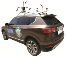
Figure 1.
Experimental platform of JJUV-6 unmanned vehicle.
-
Figure 2.
Correction chart of the point cloud coordinate.
-
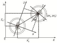
Figure 3.
Schematic diagram of calibration model.
-
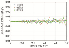
Figure 4.
Effect of the additional angular deviation on the mean of the angular deviation.
-
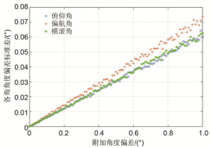
Figure 5.
Effect of the additional angular deviation on the standard deviation of the angular deviation.
-
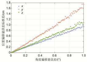
Figure 6.
Effect of the rotation angular deviation on the mean of the positional deviation.
-
Figure 7.
Effect of the rotation angular deviation on the standard deviation of the positional deviation.
-
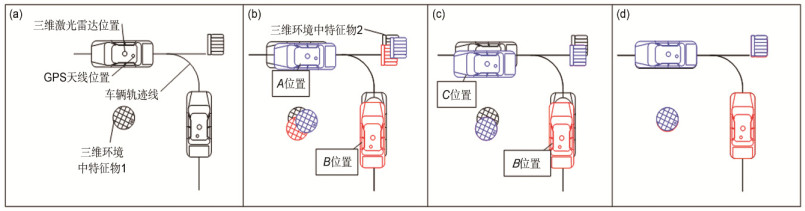
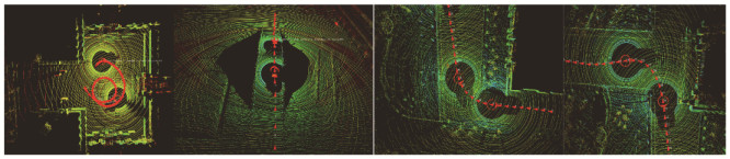
Figure 8.
Point cloud pairs in the partial acquisition scenes.
-
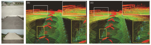
Figure 9.
Comparison of 3-dimensional reconstruction results before and after calibration on the slope. (a) The environment map. (b) The map of the point cloud before calibration. (c) The map of the point cloud after calibration.
-
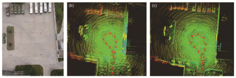
Figure 10.
Comparison of 3-dimensional reconstruction result before and after calibration at the corner. (a) The environment map. (b) The map of the point cloud before calibration. (c) The map of the point cloud after calibration.


