
 E-mail Alert
 RSS
RSS
| Citation: |
Guan Yin, Wang Xiangjun, Yin Lei, et al. Monocular position and pose measurement method based on surface topography of object[J]. Opto-Electronic Engineering, 2018, 45(1): 170522. doi: 10.12086/oee.2018.170522

|
Monocular position and pose measurement method based on surface topography of object
-
Abstract
In order to obtain the change of posture of moving objects in wind tunnel experiment, a method of single-camera visual pose measurement based on three-dimensional topography model of object surface is proposed. The method uses the multi-perspective imaging principle to solve the target pose, obtains the feature corner point on the target as the characteristic point needed for the solution, and proposes to use target's 3D surface topography information to obtain the geometric relationships between feature points. In this paper, the accuracy of the measurement method is verified under the laboratory conditions. The average accuracy of displacement is 0.23 mm and the mean square error is 0.234 mm. The accuracy of the pitch angle, yaw angle and roll angle are 0.08°, 0.1°and 0.09°, respectively, and the mean square error are 0.485°, 0.312°and 0.442°. The experimental results show that the method can be used for practical measurement.-
Keywords:
- machine vision /
- pose measurement /
- monocular vision /
- feature match /
- surface topography /
- 3D reconstruction
-

-
References
[1] 苗锡奎, 朱枫, 郝颖明.多像机非共视场的非合作飞行器位姿测量方法[J].红外与激光工程, 2013, 42 (3): 709-715. Miao X K, Zhu F, Hao Y M. Pose measurement method for non-cooperative space vehicle using multiple non-overlapping cameras[J]. Infrared and Laser Engineering, 2013, 42 (3): 709-715. [2] 刘巍, 陈玲, 马鑫, 等.基于彩色图像的高速目标单目位姿测量方法[J].仪器仪表学报, 2016, 37 (3): 675-682. Liu W, CHEN L, Ma X, et al. Monocular position and pose measurement method for high-speed targets based on colored images[J]. Chinese Journal of Scientific Instrument, 2016, 37 (3): 675-682. [3] 宋薇, 周扬.基于CAD模型的单目六自由度位姿测量[J].光学 精密工程, 2016, 24 (4): 882-891. Song W, Zhou Y. Estimation of monocular vision 6-DOF pose based on CAD model[J]. Optics and Precision Engineering, 2016, 24 (4): 882-891. [4] Rublee E, Rabaud V, Konolige K, et al. ORB: an efficient alternative to SIFT or SURF[C]//Proceedings of 2011 IEEE International Conference on Computer Vision, 2012: 2564-2571. http://ieeexplore.ieee.org/abstract/document/6126544/ [5] Li S Q, Xu C, Xie M. A Robust O(n) solution to the perspective-n-point problem[J]. IEEE Transactions on Pattern Analysis and Machine Intelligence, 2012, 34 (7): 1444-1450. doi: 10.1109/TPAMI.2012.41 [6] Heinly J, Dunn E, Frahm J M. Correcting for duplicate scene structure in sparse 3D reconstruction[C]//Proceedings of the 13th European Conference on Computer Vision, 2014: 780-795. https://link.springer.com/chapter/10.1007/978-3-319-10593-2_51 [7] Wu C C. Towards linear-time incremental structure from motion[C]//Proceedings of 2013 International Conference on 3D Vision-3DV, 2013: 127-134. http://ieeexplore.ieee.org/abstract/document/6599068/ [8] Hartley R, Zisserman A. Multiple View Geometry in Computer Vision[M]. 2nd ed. Cambridge: Cambridge University Press, 2003. [9] Triggs B, Mclauchlan P F, Hartley R I, et al. Bundle adjustment-a modern synthesis[C]//Proceedings of the International Workshop on Vision Algorithms: Theory and Practice, 1999: 298-372. https://link.springer.com/chapter/10.1007/3-540-44480-7_21 [10] Furukawa Y, Ponce J. Accurate, dense, and robust multiview stereopsis[C]//Proceedings of IEEE Conference on Computer Vision and Pattern Recognition, 2007: 1-8. http://ieeexplore.ieee.org/abstract/document/5226635/ [11] 于雅楠. 微型旋翼飞行体自适应气动外形抗扰动特性研究[D]. 天津: 天津大学, 2012. Yu Y N. Research on anti-disturbance performance of adaptive aerodynamic shape for hovering micro air vehicle[D]. Tianjin: Tianjin University, 2012. http://cdmd.cnki.com.cn/Article/CDMD-10056-1013039498.htm [12] Lowe D G. Object recognition from local scale-invariant features[C]//Proceedings of the Seventh IEEE International Conference on Computer Vision, 1999, 2: 1150-1157 http://ieeexplore.ieee.org/abstract/document/790410/ [13] Men H, Gebre B, Puchiraju K. Color point cloud registration with 4D ICP algorithm[C]//Proceedings of 2011 IEEE International Conference on Robotics and Automation, 2011: 1511-1516. http://ieeexplore.ieee.org/abstract/document/5980407/ [14] Bian J W, Lin W Y, Matsushita Y, et al. GMS: grid-based motion statistics for fast, ultra-robust feature correspondence[C]//Proceedings of 2017 IEEE Conference on Computer Vision and Pattern Recognition (CVPR), 2017: 2828-2837. [15] Mur-artal R, Montiel J M M, Tardos J D. Orb-slam: a versatile and accurate monocular SLAM system[J]. IEEE Transactions on Robotics, 2015, 31 (5): 1147-1163. doi: 10.1109/TRO.2015.2463671 [16] Mur-artal R, Tardos J D. Orb-slam2: an open-source SLAM system for monocular, stereo, and RGB-D cameras[J]. IEEE Transactions on Robotics, 2017, 33 (5): 1255-1262. doi: 10.1109/TRO.2017.2705103 -
Overview

Overview: In order to obtain the change of posture of moving objects in wind tunnel experiment, this paper presents a single camera pose and position measurement method which integrates the three-dimensional topography of object surface. The traditional monocular visual pose measurement method has to install optical mark points on the object. The 3D coordinate of the mark point has been determined at the time of installation. Then get the image coordinate of the optical mark point from pictures to calculate the pose change of the object. The disadvantages of the traditional calculation method are the complicated steps, the number of mark points is too few and they can easily be blocked, and they will distort the surface structure of the object. The surface of the measured object cannot install optical mark point, so the method needs to use the object's own image properties to set feature points.
The measurement method proposed takes multi-point perspective imaging theory as the basis for solving the pose change of objects, takes the image feature corner of the object as the feature point, and then obtains the three-dimensional coordinates of the feature points by using the three-dimensional topography model of the object surface. The three-dimensional topography model of an object is obtained using the SFM multi-view 3D reconstruction method. Finally, the RPnP algorithm is used to calculate the image coordinates and the three-dimensional coordinates of the feature points to obtain the pose change of the object.
The basic principle of pose solution is introduced. The process of SFM reconstruction, feature point matching and filtering process based on grid motion estimation are introduced briefly. The method of using 3D surface topography model to calculate the image feature corner's 3D coordinates is described in detail. And analyze the characteristics of three-dimensional coordinates of the extraction accuracy.
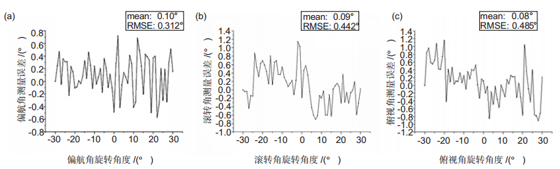
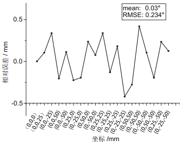
The experiment is carried out under laboratory conditions to verify the accuracy of the measurement method. At the observation distance of 400 mm, the error of the average displacement measurement is 0.03 mm and the root mean square error is 0.234 mm. The average error of pitch angle, yaw angle and roll angle are 0.08°, 0.1° and 0.09°, RMSE are 0.485°, 0.312° and 0.442°. Experimental results show that the method can be used for practical measurement accuracy.
-
Access History
Figures(10)
Tables(2)
Article Metrics


Export File
Citation
Guan Yin, Wang Xiangjun, Yin Lei, et al. Monocular position and pose measurement method based on surface topography of object[J]. Opto-Electronic Engineering, 2018, 45(1): 170522. doi: 10.12086/oee.2018.170522
Format
Content
 DownLoad:

-
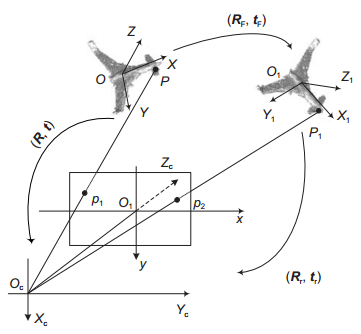
Figure 1.
The relationship between the target and the camera before and after movement
-
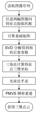
Figure 2.
SFM reconstruction process
-
Figure 3.
The target's point cloud using 3D reconstruction
-
Figure 4.
Simulation results of 3D coordinate error
-
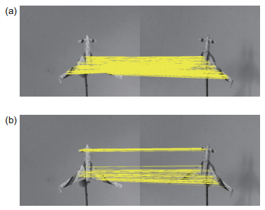
Figure 5.
Comparison of matching results. (a) GMS matching results; (b) RANSAC matching results
-
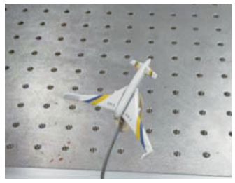
Figure 6.
The aircraft model to be tested
-
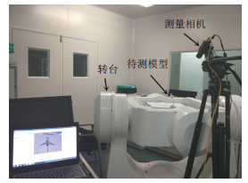
Figure 7.
The experiment on turntable
-
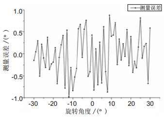
Figure 8.
Angle measurement error results. (a) Yaw angle measurement error; (b) Roll angle measurement error; (c) Pitch angle measurement error
-
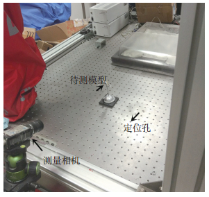
Figure 9.
Distance measurement experiment
-
Figure 10.
Distance measurement experiment results


