 E-mail Alert
 RSS
RSS
| Citation: |
Chen Zhongyu, Jiang Haibo, Sun Xiuhui, et al. Design of arrayed multi-wavelength UVLED ink curing system[J]. Opto-Electronic Engineering, 2019, 46(2): 180252. doi: 10.12086/oee.2019.180252

|
Design of arrayed multi-wavelength UVLED ink curing system
-
Abstract
Compared with mercury-vapor lamp, ultraviolet (UV) LED suffers from the disadvantage of having a single wavelength, which is not fully compatible with the existing photoinitiator of ultraviolet ink. It is difficult using UVLEDs to achieve the curing effect comparable to what mercury-vapor lamp can do. This article presents a design of UVLED ink curing system that provides evenly mixed light with multiple wavelengths. We put a UVLED array with three wavelengths on a cambered surface and achieved uniform illumination in ink curing area by using optical freeform surface. By adding the adjusting of the tilt angle, we solved the dilemma of uniform wavelength mixing and uniform illumination. The ray tracing simulation results show that an illumination spot with uniform wavelength mixing, an average illumination of 110.7 mW/cm2, and an illuminance uniformity of 0.82 is obtained on a target surface 600 mm away from the light source. This design is expected to simulate the multi-spectral illumination effect of mercury-vapor lamps, which can promote the application of UVLEDs in ink curing.-
Keywords:
- optical design /
- LED array /
- ink curing /
- mercury lamp /
- uniformity
-

-
References
[1] 谢军, 游立德, 侯文杰.光固化快速成形中的紫外LED光源系统实验研究[J].光电工程, 2009, 36(2): 100–104. doi: 10.3969/j.issn.1003-501X.2009.02.019 Xie J, You L D, Hou W J. Experimental research of ultraviolet LED source system in stereolithography apparatus[J]. Opto-Electronic Engineering, 2009, 36(2): 100–104. doi: 10.3969/j.issn.1003-501X.2009.02.019 [2] 韩秋漪, 李思琪, 李明昊, 等.高功率密度紫外LED封装模组及其光固化应用[J].照明工程学报, 2017, 28(1): 21–29. Han Q Y, Li S Q, Li M H, et al. High power-density UV-LED package modules and their application in curing[J]. China Illuminating Engineering Journal, 2017, 28(1): 21–29. [3] 葛惊寰, 刘春林. UV油墨固化光源的比较[J].丝网印刷, 2013(2): 24–28. [4] Pelka D G, Patel K. An overview of LED applications for general illumination[J]. Proceedings of SPIE, 2003, 5186: 15–26. doi: 10.1117/12.509164 [5] 郝剑, 荆雷, 王尧, 等.阵列型紫外LED匀光照明系统设计[J].光学学报, 2015, 35(10): 1022003. Hao J, Jing L, Wang Y, et al. Design of uniform illumination for array LED[J]. Acta Optica Sinica, 2015, 35(10): 1022003. [6] 黄慧, 李湘宁, 汪宇青. LED复合椭球面聚光器的设计[J].光电工程, 2015, 42(3): 89–94. doi: 10.3969/j.issn.1003-501X.2015.03.015 Huang H, Li X N, Wang Y Q. Design for LED compound elliptical concentrator[J]. Opto-Electronic Engineering, 2015, 42(3): 89–94. doi: 10.3969/j.issn.1003-501X.2015.03.015 [7] 许文海, 赵欢, 芦永军. LED阵列式紫外固化光源光学系统设计[J].光学精密工程, 2007, 15(7): 1032–1037. doi: 10.3321/j.issn:1004-924X.2007.07.007 Xu W H, Zhao H, Lu Y J. Design of an optical system for UV curing source with LED array[J]. Optics and Precision Engineering, 2007, 15(7): 1032–1037. doi: 10.3321/j.issn:1004-924X.2007.07.007 [8] Liu H, Tang Z R, Shi T L, et al. Optical and thermal modeling of ultraviolet-LED array packaging for curing application[J]. Proceedings of SPIE, 2009, 7279: 7279K. [9] 向昌明, 文尚胜, 陈颖聪, 等.紫外光LED固化面光源光学系统设计[J].发光学报, 2016, 37(12): 1507–1513. Xiang C M, Wen S S, Chen Y C, et al. Optical system design of LED area source for ultraviolet curing[J]. Chinese Journal of Luminescence, 2016, 37(12): 1507–1513. [10] 罗毅, 张贤鹏, 王霖, 等.半导体照明中的非成像光学及其应用[J].中国激光, 2008, 35(7): 963–971. doi: 10.3321/j.issn:0258-7025.2008.07.001 Luo Y, Zhang X P, Wang L, et al. Non-imaging optics and its application in solid state lighting[J]. Chinese Journal of Lasers, 2008, 35(7): 963–971. doi: 10.3321/j.issn:0258-7025.2008.07.001 [11] 杨毅, 钱可元, 罗毅.一种新型的基于非成像光学的LED均匀照明系统[J].光学技术, 2007, 33(1): 0110. Yang Y, Qian K Y, Luo Y. A novel LED uniform illuminance system based on nonimaging optics[J]. Optical Technique, 2007, 33(1): 0110. [12] 魏彬, 林庆. UV-LED在光固化领域的应用现况和趋势[J].中国高新技术企业, 2017(11): 92–93. Wei B, Lin Q. Application status and trend of Ultraviolet led in the field of light curing[J]. China High-Tech Enterprises, 2017(11): 92–93. [13] 张蕾. UV-LED固化技术发展趋势[J].电子元件与材料, 2015, 34(6): 99–100. [14] 赵亚辉, 范长江.组合式发光二极管路灯反射器的设计[J].中国光学, 2012, 5(5): 520–524. Zhao Y H, Fan C J. Design of combined reflectors used in LED street lamps[J]. Chinese Optics, 2012, 5(5): 520–524. [15] Su Z P, Xue D L, Ji Z C. Designing LED array for uniform illumination distribution by simulated annealing algorithm[J]. Optics Express, 2012, 20(S6): A843–A855. doi: 10.1364/OE.20.00A843 [16] 丁毅, 郑臻荣, 顾培夫.实现LED照明的自由曲面透镜设计[J].光子学报, 2009, 38(6): 1486–1490. Ding Y, Zheng Z R, Gu P F. Freeform lens design for LED illmination[J]. Acta Photonica Sinica, 2009, 38(6): 1486–1490. -
Overview

Overview: Ultraviolet light emitting diode (UV-LED) with the advantages of small volume, high luminous efficiency and long life, shows a good prospect in replacing the traditional mercury lamp for the ink curing. At present, there have been many researches on UV-LED light source array, which mainly focus on how to improve the uniformity and illuminance of the spot formed by LED array on the target surface, and use secondary light distribution design to optimize. However, these researches are all aimed at UV-LED of single wavelength, and obtain curing spot that meets demand by theoretically calculating the arrangement spacing and number of LEDs. The ink for traditional UV curing is all matched with the spectrum of mercury lamp, but the curing effect of UV-LED with single wavelength and narrow spectrum is often different from mercury lamp, so the curing effect is unsatisfactory, which block the spread of UV-LED in ink curing. In present, the central wavelength of commercial UV-LED covers the main UV spectra of mercury lamp. The wavelength range is from 250 nm to 435 nm, and the absorption bandwidth of the photoinitiator is large. In theory, combining UV-LEDs of multiple wavelengths is a feasible way to solve the problem of unsatisfactory single-wavelength UV-LED curing effect. Based on this idea, this paper presents a design method of arrayed multi-wavelength UV LED ink curing system and applies it to the design of three-wavelength UV LED ink curing system. A freeform lens is used to even the light of the LED, and the technical problems of uniform wavelength mixing and uniform illumination are solved by the design of freeform lens and its tilt. The designing steps are as follows: firstly, a freeform lens should be designed to form uniform illuminance distribution for single LED, and then the total number of demanded LEDs is determined according to the required illuminance. Finally, each LED and its homogenization lens are arrayed on the curved substrate. The final entity is shown in the figure. The ray tracing simulation results show that an average illuminance of 110.7 mW/cm2 and an illuminance uniformity of 0.82 are obtained on a target surface 600 mm away from the light source. This method is not limited to the use of three wavelengths and is expected to solve the problem that UV-LED in ink curing cannot be fully compatible with existing photoinitiators of UV inks. It is also expected to promote the application of UVLEDs in ink curing by this study.
-
Access History
Figures(8)
Tables(1)
Article Metrics
Export File
Citation
Chen Zhongyu, Jiang Haibo, Sun Xiuhui, et al. Design of arrayed multi-wavelength UVLED ink curing system[J]. Opto-Electronic Engineering, 2019, 46(2): 180252. doi: 10.12086/oee.2019.180252
Format
Content
 DownLoad:


-
Figure 1.
Vertical illumination schematic of LED with different wavelengths
-
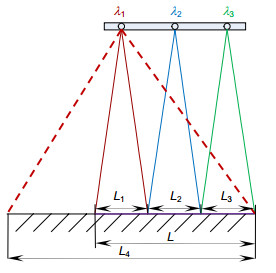
Figure 2.
Oblique illumination schematic of LED with different wavelengths
-
Figure 3.
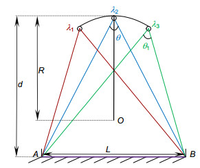
Light geometry diagram
-
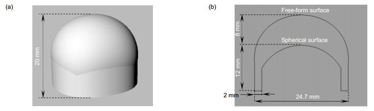
Figure 4.
(a) Model of free-form lens; (b) Sections in x and y directions
-
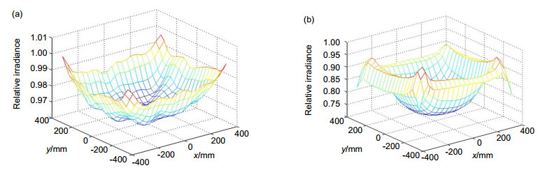
Figure 5.
Irradiance distribution of target surface lighting spot. (a) Point source; (b) LED source
-
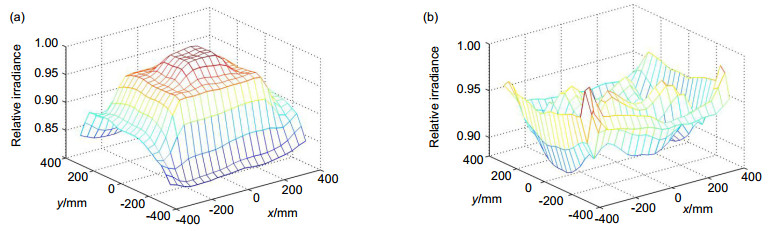
Figure 6.
Irradiance distribution of optimized target surface lighting spot. (a) Point source; (b) LED source
-
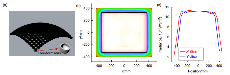
Figure 7.
(a) Model of LED source array; (b) Target surface lighting spot; (c) Illuminance distribution
-
Figure 8.
The target surface lighting spot when d changes. (a) 580 mm; (b) 600 mm; (c) 620 mm


