
 E-mail Alert
 RSS
RSS
| Citation: |
Liu Zhiyuan, Chen Lei, Zhu Wenhua, et al. Oblique incidence dynamic phase-shifting interferometer based on inclination angle deflection[J]. Opto-Electronic Engineering, 2019, 46(8): 180516. doi: 10.12086/oee.2019.180516

|
Oblique incidence dynamic phase-shifting interferometer based on inclination angle deflection
-
Abstract
An oblique incidence dynamic phase-shifting interferometer based on inclination angle deflection is proposed to quickly obtain the surface distribution of optical surface with flatness of micron dimension. A 2×2 point source array is introduced into a Michelson interference system, and the incidence angle of each point source on the interferometer cavity is adjusted precisely to induce equal phase shift. Spatial separation is realized in combination with a lens array. The four phase-shifting interferograms are captured simultaneously on a single CCD, thereby realizing dynamic measurement. The flatness of a 35 mm aperture silicon wafer is measured at oblique incidence angle of 68°, the root mean square (RMS) is 1.631 μm and peak-to-valley (PV) is 9.082 μm. The experimental results indicate that the proposed interferometer overcomes the disturbance of vibration environment and extends the measurement range of interferometer with high precision by introducing the simultaneous phase-shifting interferometry based on inclination angle deflection into the oblique incidence interference system.-
Keywords:
- interferometry /
- oblique incidence /
- dynamic interferometer /
- surface flatness
-

-
References
[1] Malacara D. Optical Shop Testing[M]. 3rd ed. New York: John Wiley & Sons, 2007: 33-59. [2] Vannoni M, Martìn I F. Surface measurements in "grazing incidence" interferometry for long x-ray mirrors: theoretical limits and practical implementations[J]. Proceedings of SPIE, 2016, 9962: 996207. doi: 10.1117/12.2238623 [3] Mizutani Y, Iwata T, Otani Y. Time-resolved vibrational surface profile measurement of ultrasonic motor using stroboscopic oblique incidence interferometer[J]. Proceedings of SPIE, 2010, 7855: 78550N. doi: 10.1117/12.871749 [4] Wen H, Kemble C K, Bennett E E. Theory of oblique and grazing incidence Talbot-Lau interferometers and demonstration in a compact source x-ray reflective interferometer[J]. Optics Express, 2011, 19(25): 25093-25112. doi: 10.1364/OE.19.025093 [5] Szwaykowski P, Bushroe F N, Castonguay R J. Interferometric system with reduced vibration sensitivity and related method: 8004687.B2[P]. 2011-12-09. [6] Millerd J E, Brock N J, Hayes J B, et al. Pixelated phase-mask dynamic interferometer[J]. Proceedings of SPIE, 2004, 5531: 304-310. doi: 10.1117/12.560807 [7] Kimbrough B T. Pixelated mask spatial carrier phase shifting interferometry algorithms and associated errors[J]. Applied Optics, 2006, 45(19): 4554-4562. doi: 10.1364/AO.45.004554 [8] Yu Y J, Peng J, Wang Z Q. Spatial phase-shifting interferential system on polarization interference and grating beam-splitting: phase-shifting error testing[J]. Journal of Physics: Conference Series, 2006, 48(1): 992-997. doi: 10.1088/1742-6596/48/1/185 [9] Zhu W H, Chen L, Zheng D H, et al. Dynamic Fizeau interferometer based on the lateral displacements of the point sources[J]. Optics and Lasers in Engineering, 2017, 91: 216-220. doi: 10.1016/j.optlaseng.2016.12.007 [10] Robledo-Sanchez C, Juarez-Salazar R, Meneses-Fabian C, et al. Phase-shifting interferometry based on the lateral displacement of the light source[J]. Optics Express, 2013, 21(14): 17228-17233. doi: 10.1364/OE.21.017228 [11] Langenbeck P. Interferometry for Precision Measurement[M]. Bellingham, Washington: SPIE, 2014: 39-53. [12] Born M, Wolf E. Principles of Optics[M]. 7th ed. Cambridge: Cambridge University Press, 1999: 261-270. [13] Geary J M. Introduction to Lens Design[M]. Viriginia: Willmann Bell, Inc, 2002: 389-396. -
Overview

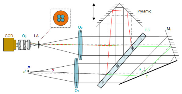
Overview: An oblique incidence dynamic phase-shifting interferometer based on inclination angle deflection is proposed to quickly obtain the surface distribution of optical surface with flatness of micron dimension. The measurement is based on the Michelson interference system. The He-Ne laser which operates at 632.8 nm is used as the light source. In combination with a phase mask grating, the four (±1, ±1) diffraction orders is selected to generate a 2×2 point source array which is introduced into the interference system as light source configuration. Adjust the distance of each point source off the optical axis precisely, the incidence angle of each point source on the interferometer cavity is changed to induce phase shift. In this work, we introduce equal phase shift interval of π/2 in the interferograms. We choose double telecentric imaging system to ensure the entire test part can be clearly imaged. By inducing a lens array into the imaging system, the four interferograms can be separated spatially on a single CCD. Then the four phase-shifting interferograms are captured simultaneously on the CCD target, and the initial phase will be retrieved exactly by employing the four-bucket algorithm, thereby realizing dynamic measurement. To analyze the measurement error which is introduced by the offset amounts of each point source, we establish a simulation model to study the effect of the collimated wavefront quality on the measurement. It is necessary to ensure that the aberrations which collimated wavefront contains smaller than λ/4, and the F-number of the collimating objective lens should be greater than 8.5. We also design the imaging system to ensure image quality through Zemax software. We build up the experiment device and choose a silicon wafer with aperture of 35 mm as the test part. The flatness of silicon wafer is about 10 μm dimension, and the measurement of the thin wafer is susceptible to vibration. Furthermore, to study the influence of the oblique incidence angle on the sensitivity factor and the range of measurement, a mathematical model based on the oblique incidence measurement is established to select the best incidence angle. Considering the sensitivity factor, the aperture of the test part, the surface reflectance and the spatial resolution, the silicon wafer is measured at oblique incidence angle of 68°, the root mean square (RMS) is 1.631 μm and peak-to-valley (PV) is 9.082 μm. The experimental results indicate that the proposed interferometer overcomes the disturbance of vibration environment and extends the measurement range of interferometer with high precision by introducing the simultaneous phase-shifting interferometry based on inclination angle deflection into the oblique incidence interference system.
-
Access History

Export File
Citation
Liu Zhiyuan, Chen Lei, Zhu Wenhua, et al. Oblique incidence dynamic phase-shifting interferometer based on inclination angle deflection[J]. Opto-Electronic Engineering, 2019, 46(8): 180516. doi: 10.12086/oee.2019.180516
Format
Content
 DownLoad:


-
Figure 1.
Optical layout of the oblique incidence interferometer
-
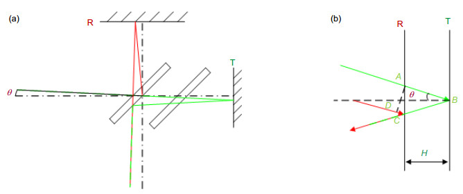
Figure 2.
Principle of phase shifting based on the variation of inclination. (a) The alternative representation of optical path in the Michelson interferometer; (b) The alternative representation of optical path in an equal-thickness interferometer
-
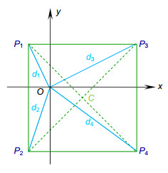
Figure 3.
The spatial distribution of point sources
-
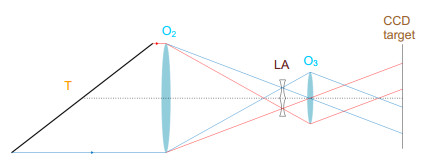
Figure 4.
Spatial splitting imaging system
-
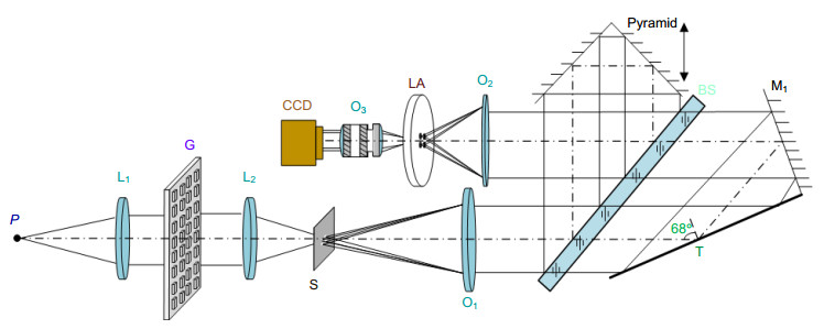
Figure 5.
Optical layout of oblique incidence interferometer based on inclination angle deflection
-
Figure 6.
Experimental device of oblique incidence interferometer based on inclination angle deflection
-
Figure 7.
Experimental results. (a) The interferograms recorded by CCD; (b) The retrieved surface distribution of silicon substrate
-
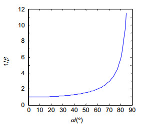
Figure 8.
Expanded measurement range with different oblique incidence angles
-
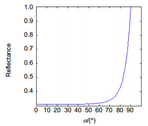
Figure 9.
Reflectance with different oblique incidence angles
-
Figure 10.
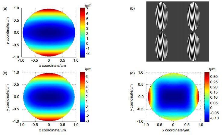
Simulation result. (a) The simultaneous phase shift interferogram; (b) Original phase; (c) Phase derived by four-step phase-shifting method; (d) Residual surface
-
Figure 11.
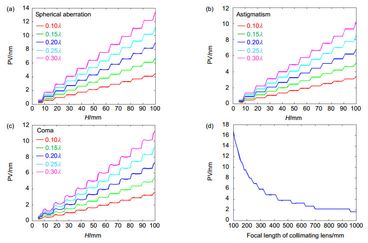
Calculation error introduced by the light deflection. (a) Collimated wavefront with spherical aberration; (b) Collimated wavefront with astigmatism; (c) Collimated wavefront with coma; (d) Relationship with focal length of collimating lens
-
Figure 12.
MTF numerical curve
-
Figure 13.
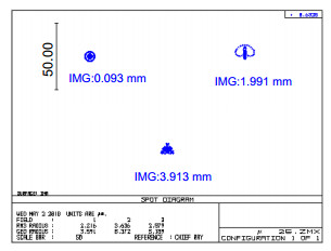
Spot diagram
-
Figure 14.
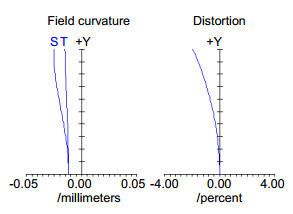
Field curvature/distortion curve


