
 E-mail Alert
 RSS
RSS
| Citation: |
Feng Z X, Cheng D W, Wang Y T. Iterative freeform lens design for prescribed irradiance on curved target. Opto-Electron Adv 3, 200010 (2020). doi: 10.29026/oea.2020.200010

|
Iterative freeform lens design for prescribed irradiance on curved target
-
Abstract
Current freeform illumination optical designs are mostly focused on producing prescribed irradiance distributions on planar targets. Here, we aim to design freeform optics that could generate a desired illumination on a curved target from a point source, which is still a challenge. We reduce the difficulties that arise from the curved target by involving its varying z-coordinates in the iterative wavefront tailoring (IWT) procedure. The new IWT-based method is developed under the stereographic coordinate system with a special mesh transformation of the source domain, which is suitable for light sources with light emissions in semi space such as LED sources. The first example demonstrates that a rectangular flat-top illumination can be generated on an undulating surface by a spherical-freeform lens for a Lambertian source. The second example shows that our method is also applicable for producing a non-uniform irradiance distribution in a circular region of the undulating surface. -

-
References
[1] Ripoll O, Kettunen V, Herzig H P. Review of iterative Fourier-transform algorithms for beam shaping applications. Opt Eng 43, 2549-2556 (2004). [2] Keren-Zur S, Avayu O, Michaeli L, Ellenbogen T. Nonlinear beam shaping with plasmonic metasurfaces. ACS Photonics 3, 117-123 (2016). [3] Cao G Y, Gan X S, Lin H, Jia B H. An accurate design of graphene oxide ultrathin flat lens based on Rayleigh-Sommerfeld theory. Opto-Electron Adv 1, 180012 (2018). [4] Komissarov V D, Boldyrev N G. The foundations of calculating specular prismatic fittings. Trudy VEI 43, 6-61 (1941). [5] Schruben J S. Formulation of a reflector-design problem for a lighting fixture. J Opt Soc Am 62, 1498-1501 (1972). doi: 10.1364/JOSA.62.001498 [6] Wu R M, Xu L, Liu P, Zhang Y Q, Zheng Z R et al. Freeform illumination design: a nonlinear boundary problem for the elliptic Monge-Ampére equation. Opt Lett 38, 229-231 (2013). [7] Ries H, Muschaweck J. Tailored freeform optical surfaces. J Opt Soc Am A 19, 590-595 (2002). doi: 10.1364/JOSAA.19.000590 [8] Oliker V. Mathematical aspects of design of beam shaping surfaces in geometrical optics. In Trends in Nonlinear Analysis 191-222 (Springer-Verlag, Berlin, Heidelberg, 2002); https://doi.org/10.1007/978-3-662-05281-5_4. [9] Wang X J. On the design of a reflector antenna Ⅱ. Calc Var Partical Differ Equ 20, 329-341 (2004). doi: 10.1007/s00526-003-0239-4 [10] Fournier F R, Cassarly W J, Rolland J P. Fast freeform reflector generation using source-target maps. Opt Express 18, 5295-5304 (2010). [11] Michaelis D, Schreiber P, Bräuer A. Cartesian oval representation of freeform optics in illumination systems. Opt Lett 36, 918-920 (2011). [12] Canavesi C, Cassarly W J, Rolland J P. Target flux estimation by calculating intersections between neighboring conic reflector patches. Opt Lett 38, 5012-5015 (2013). [13] Parkyn W A. Illumination lenses designed by extrinsic differential geometry. Proc SPIE 3482, 389-396 (1998). doi: 10.1117/12.322042 [14] Wang L, Qian K Y, Luo Y. Discontinuous free-form lens design for prescribed irradiance. Appl Opt 46, 3716-3723 (2007). [15] Bäuerle A, Bruneton A, Wester R, Stollenwerk J, Loosen P. Algorithm for irradiance tailoring using multiple freeform optical surfaces. Opt Express 20, 14477-14485 (2012). [16] Yue Y H, Iwasaki K, Chen B Y, Dobashi Y, Nishita T. Poisson-based continuous surface generation for goal-based caustics. ACM Trans Graph 33, 31 (2014). [17] Schwartzburg Y, Testuz R, Tagliasacchi A, Pauly M. High-contrast computational caustic design. ACM Trans Graph 33, 74 (2014). [18] Ma D L, Feng Z X, Liang R G. Tailoring freeform illumination optics in a double-pole coordinate system. Appl Opt 54, 2395-2399 (2015). [19] Feng Z X, Froese B D, Liang R G. Freeform illumination optics construction following an optimal transport map. Appl Opt 55, 4301-4306 (2016). [20] Mao X L, Xu S B, Hu X R, Xie Y J. Design of a smooth freeform illumination system for a point light source based on polar-type optimal transport mapping. Appl Opt 56, 6324-6331 (2017). [21] Bruneton A, Bäuerle A, Wester R, Stollenwerk J, Loosen P. Limitations of the ray mapping approach in freeform optics design. Opt Lett 38, 1945-1947 (2013). [22] Wester R, Völl A, Berens M, Stollenwerk J, Loosen P. Solving the Monge-Ampère equation on triangle-meshes for use in optical freeform design. Proc SPIE 10693, 1069307 (2018). [23] Bruneton A, Bäuerle A, Wester R, Stollenwerk J, Loosen P. High resolution irradiance tailoring using multiple freeform surfaces. Opt Express 21, 10563-10571 (2013). [24] Bösel C, Gross H. Single freeform surface design for prescribed input wavefront and target irradiance. J Opt Soc Am A 34, 1490-1499 (2017). doi: 10.1364/JOSAA.34.001490 [25] Desnijder K, Hanselaer P, Meuret Y. Ray mapping method for off-axis and non-paraxial freeform illumination lens design. Opt Lett 44, 771-774 (2019). [26] Doskolovich L L, Bykov D A, Mingazov A A, Bezus E A. Optimal mass transportation and linear assignment problems in the design of freeform refractive optical elements generating far-field irradiance distributions. Opt Express 27, 13083-13097 (2019). [27] Bykov D A, Doskolovich L L, Mingazov A A, Bezus E A, Kazanskiy N L. Linear assignment problem in the design of freeform refractive optical elements generating prescribed irradiance distributions. Opt Express 26, 27812-27825 (2018). [28] Prins C R, Beltman R, ten Thije Boonkkamp J H M, IJzerman W L, Tukker T W. A least-squares method for optimal transport using the Monge-Ampère equation. SIAM J Sci Comput 37, B937-B961 (2015). doi: 10.1137/140986414 [29] Romijn L B, ten Thije Boonkkamp J H M, IJzerman W L. Freeform lens design for a point source and far-field target. J Opt Soc Am A 36, 1926-1939 (2019). doi: 10.1364/JOSAA.36.001926 [30] Wei S L, Zhu Z B, Fan Z C, Ma D L. Least-squares ray mapping method for freeform illumination optics design. Opt Express 28, 3811-3822 (2020). [31] Feng Z X, Cheng D W, Wang Y T. Iterative wavefront tailoring to simplify freeform optical design for prescribed irradiance. Opt Lett 44, 2274-2277 (2019). [32] Karakhanyan A, Wang X J. On the reflector shape design. J Differ Geom 84, 561-610 (2010). doi: 10.4310/jdg/1279114301 [33] Wu R M, Yang L, Ding Z H, Zhao L F, Wang D D et al. Precise light control in highly tilted geometry by freeform illumination optics. Opt Lett 44, 2887-2890 (2019). [34] Sun X, Kong L B, Xu M. Uniform illumination for nonplanar surface based on freeform surfaces. IEEE Photonics J 11, 2200511 (2019). [35] Kelley C T. Solving nonlinear equations with Newton's method. (Philadelphia, Society for Industrial and Applied Mathematics (SIAM), 2003). https://archive.siam.org/books/fa01/nsoli.m. [36] Luo Y, Feng Z X, Han Y J, Li H T. Design of compact and smooth free-form optical system with uniform illuminance for LED source. Opt Express 18, 9055-9063 (2010). [37] Feng Z X, Luo Y, Han Y J. Design of LED freeform optical system for road lighting with high luminance/illuminance ratio. Opt Express 18, 22020-22031 (2010). [38] Mao X L, Li H T, Han Y J, Luo Y. Two-step design method for highly compact three-dimensional freeform optical system for LED surface light source. Opt Express 22, A1491-A1506 (2014). [39] Wester R, Müller G, Völl A, Berens M, Stollenwerk J et al. Designing optical free-form surfaces for extended sources. Opt Express 22, A552-A560 (2014). [40] Brand M, Aksoylar A. Sharp images from freeform optics and extended light sources. In Frontiers in Optics 2016 (Optical Society of America, 2016); https://doi.org/10.1364/FIO.2016.FW5H.2. -
Access History
Figures(8)
Article Metrics


Export File
Citation
Feng Z X, Cheng D W, Wang Y T. Iterative freeform lens design for prescribed irradiance on curved target. Opto-Electron Adv 3, 200010 (2020). doi: 10.29026/oea.2020.200010
Format
Content
 DownLoad:

-
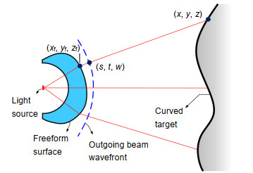
Figure 1.
Sketch of the design geometry.
-
Figure 2.
The rectangular (u, v) grid (a) is transformed into a circular (u', v') grid (b) which is used as the stereographic coordinates (c).
-
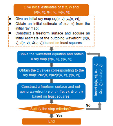
Figure 3.
The flow diagram of the new IWT procedure for a curved target.
-
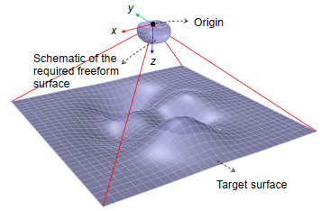
Figure 4.
The desired curved target.
-
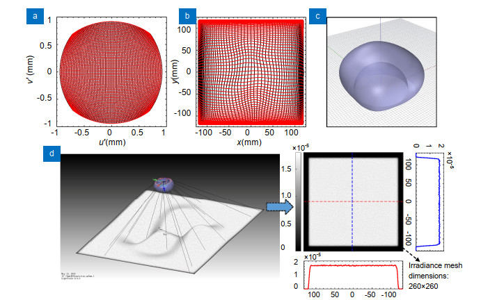
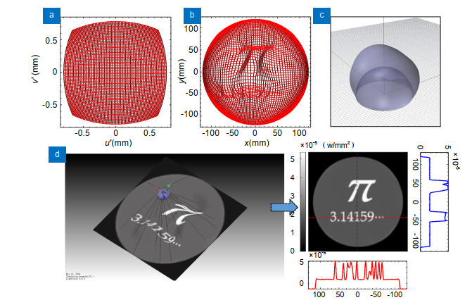
Figure 5.
(a) The (u′, v′) grid corresponding to a uniform (u, v) grid on Ω={(u, v)|-0.94≤u≤0.94, -0.94≤v≤0.94} and (b) the final target grid for the first design (only showing 64×64 grid points for better visualization); (c) The final 3D freeform lens model and (d) its simulation results for a point like source (size: 10-3 mm×10-3 mm). (The unit of the irradiance: W/mm2)
-
Figure 6.
(a) The (u′, v′) grid corresponding to a uniform (u, v) grid on Ω={(u, v)|-0.8≤u≤0.8, -0.8≤v≤0.8} and (b) the final target grid for the second design (only showing 64×64 grid points for better visualization); (c) The final 3D freeform lens model and (d) its simulation results for a point like source (size: 10-3 mm×10-3 mm). (The unit of the irradiance: W/mm2)
-
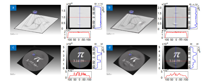
Figure 7.
Simulated irradiance distributions for the first lens design when the source size is changed into (a) 1 mm× 1mm and (b) 2 mm× 2 mm respectively; simulated irradiance distributions for the second lens design when the source size is changed into (c) 1 mm × 1mm and (d) 2 mm × 2 mm respectively.
-
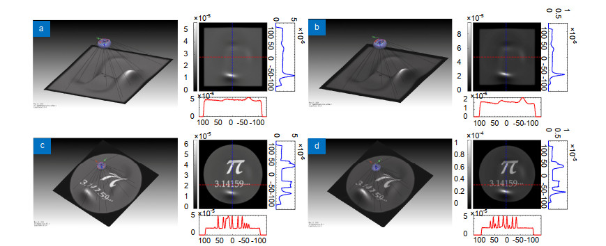
Figure 8.
Simulated irradiance distributions for the first lens design when the source-lens system is (a) 5 mm and (b) 10 mm closer to the target. Simulated irradiance distributions for the second lens design when the source-lens system is (c) 5 mm and (d) 10 mm closer to the target.


