
 E-mail Alert
 RSS
RSS
| Citation: |

|
Error model analysis and correlation correction of Hartmann's focimeter
-
Abstract
In order to reduce the error and improve the measurement accuracy, a more detailed error model is established for the Hartmann method of focal power measurement in this paper. It focuses on the analysis of several problems that cause the error of refraction problems, including the dispersion error of the light source, the inaccurate of the photodetector's central positing, the tilt of lens, misalignment between incidence axis and main axis of lens, and the incident light and the lens are not perpendicular. At last, it is concluded that the inaccuracy of the center extraction on the photodetector will cause a large error to the final result. For all these reasons, a method of dual bilinear interpolation combined with a fitting method to find the centroid is proposed, proving its effectiveness and accuracy.-
Keywords:
- Hartmann diaphragm /
- focimeter /
- error model /
- image processing /
- centroid calculation
-

-
References
[1] Mumzhiu A M, Strakun G I. Investigation of an automatic lensometer[J]. Meas Tech, 1972, 15(4): 538-541. doi: 10.1007/BF00823265 [2] Cordero I. Understanding and caring for a lensmeter[J]. Comm Eye Health J, 2016, 29(94): 37. [3] Barbosa E A, Silva D M, Nascimento C E, et al. Progressive power lens measurement by low coherence speckle interferometry[J]. Opt Lasers Eng, 2013, 51(7): 898-906. doi: 10.1016/j.optlaseng.2013.02.007 [4] Aono Y, Negishi M, Takano J. Development of large aperture spherical lens with glass molding[J]. Proc SPIE, 2000, 4231: 16-23. doi: 10.1117/12.402759 [5] Fu X H, Dong H, Jia Z H, et al. Research on processing technology of odd-form off-axis aspherical lens[J]. Proc SPIE, 2014, 9281: 92812F. doi: 10.1117/12.2068113 [6] Ceyhan U, Henning T, Fleischmann F, et al. Measurements of aberrations of aspherical lenses using experimental ray tracing[J]. Proc SPIE, 2011, 8082: 80821K-1. [7] 杨并上, 廖海洋, 王涵. 数字投影式焦度计误差分析及校正方法[J]. 光学精密工程, 2004, 12(S1): 136-139. Yang B S, Liao H Y, Wang H. Error analysis and correction of digital projection focimeter[J]. Opt Precision Eng, 2004, 12(S1): 136-139. [8] 朱林泉, 朱苏磊. 焦度计的测量误差和校正方法[J]. 仪器仪表学报, 2006, 27(S2): 1284-1285. Zhu L Q, Zhu S L. Measuring error and correcting method of the dioptometer[J]. Chin J Sci Instrum, 2006, 27(S2): 1284-1285. [9] 赵俊奇, 郭智勇, 闫洁. 一种图像处理的全自动焦度计[J]. 光电工程, 2012, 39(3): 34-39. doi: 10.3969/j.issn.1003-501X.2012.03.007 Zhao J Q, Guo Z Y, Yan J. An image processing auto lensmeter[J]. Opto-Electron Eng, 2012, 39(3): 34-39. doi: 10.3969/j.issn.1003-501X.2012.03.007 [10] 沈春花. 浅谈色散对焦度计检测的影响[J]. 北京生物医学工程, 2010, 29(5): 534-537. doi: 10.3969/j.issn.1002-3208.2010.05.22. Shen C H. Briefing the influence of dispersion on detecting lensmeter[J]. Beijing Biomed Eng, 2010, 29(5): 534-537. doi: 10.3969/j.issn.1002-3208.2010.05.22. [11] Snoeys W. Monolithic CMOS sensors for high energy physics[J]. Nucl Instrum Meth Phys Res Sect A Accel Spectrometers Detect Assoc Equip, 2019, 924: 51-58. doi: 10.1016/j.nima.2018.06.034 [12] Mahato S B, de Ridder J, Meynants G, et al. Measuring intra-pixel sensitivity variations of a CMOS image sensor[J]. IEEE Sens J, 2018, 18(7): 2722-2728. doi: 10.1109/JSEN.2018.2798698 [13] Song W T, Cheng J J, Liu Y, et al. Three-dimensional image authentication using binarized images in double random phase integral imaging[J]. Chin Opt Lett, 2019, 17(5): 21-25. [14] Roy S, Bhattacharyya D, Bandyopadhyay S K, et al. An improved brain MR image binarization method as a preprocessing for abnormality detection and features extraction[J]. Front Comp Sci, 2017, 11(4): 717-727. doi: 10.1007/s11704-016-5129-y [15] Cheng M M, Liu Y, Lin W Y, et al. BING: Binarized normed gradients for objectness estimation at 300fps[J]. Comput Vis Med, 2019, 5(1): 3-20. doi: 10.1007/s41095-018-0120-1 -
Overview

Overview: The focus meter mainly adopts the Hartmann diaphragm measurement method. The parallel light passes through the lens and the Hartmann diaphragm plate on the photodetector image. The spot image formed without the lens has a corresponding change in position, according to the position of the spot. The change in distance calculates the optical parameters of the lens' top power. This method can not only effectively reduce the error caused by human but also accurately measure the optical parameters of the lens. However, there is no complete error model for autofocus focal meters. Therefore, the relatively perfect error model analysis of the Hartmann measurement method is beneficial to the error correction of the subsequent focal meter measurement. The inaccuracy of the actual diopter measurement is caused by the dispersion error of the light source, the inaccurate of the photodetector's central positing, the tilt of lens, and the misalignment between the incidence axis and the main axis of the lens. Through the analysis of the error model, the inaccurate positioning of the CMOS photodetector centroid will lead to larger errors. Therefore, a dual bilinear method is proposed. Combining the interpolation method with the fitting method, one can find the center of mass, and it's the method is effectiveness and accuracy. The conclusion is obtained through analysis. The light source is the green LED light source. Ignoring the distance between the lens and the CMOS photodetector, the Abbe number correction can be eliminated and the complexity of the algorithm can be reduced, resulting in a small error in the final measurement result. For the errors caused by the lens tilt and the misalignment between the incidence axis and the main axis of the lens. The larger misalignment above the large diopter error, and it affects the accuracy of the experimental results. In the experiment, it is necessary to keep the lens and the incident light is perpendicular to each other. In practice, the error model described in this article can be used for correction. Moreover, if the location of the spot center of mass on the CMOS photodetector is inaccurate, a larger error will occur. Therefore, combining the fitting method in this article with the double bilinear interpolation can improve the accuracy of the spot center of mass and ensure the high positioning of the center of mass, ensuring the accuracy of the diopter measurement results.
-
Access History

Figures(14)
Tables(1)
Article Metrics


Export File
Citation
Format
Content
 DownLoad:


-
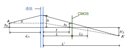
Figure 1.
Measuring model for the Hartmann method
-
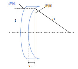
Figure 2.
Actual position diagram of the lens and diaphragm
-
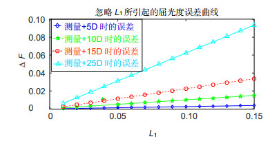
Figure 3.
Curves of diopter error caused by neglecting L1
-
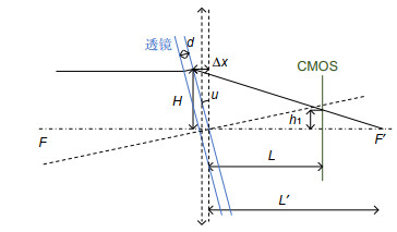
Figure 4.
Measurement model of lens tilt
-
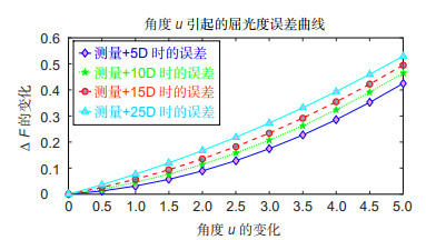
Figure 5.
Variation of diopter error caused by lens deflection
-
Figure 6.
A lens model for an external light spot of spindle
-
Figure 7.
Error curve caused by the deflection angle between the optical axis and lens axis
-
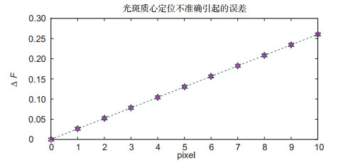
Figure 8.
Diopter error curve caused by pixel difference
-
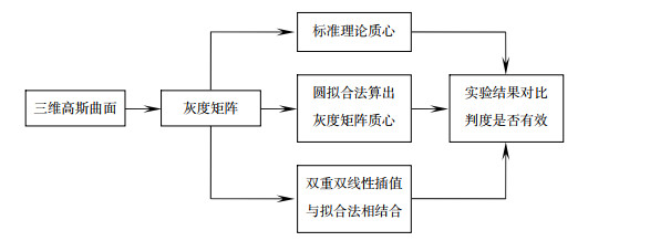
Figure 9.
Flow chart of the whole algorithm
-
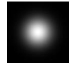
Figure 10.
Gray image corresponding to the Gaussian spot
-
Figure 11.
Binary image corresponding to the Gaussian spot
-
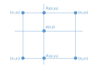
Figure 12.
Schematic diagram of the bilinear interpolation algorithm
-
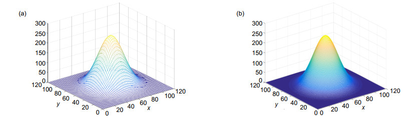
Figure 13.
(a) Gauss surface figure before interpolation; (b) Gauss surface figure after interpolation
-
Figure 14.
(a) Image edge information before interpolation; (b) Image edge information after interpolation


