
 E-mail Alert
 RSS
RSS
| Citation: |
Liu S, Zhang Z H, Gao N, et al. Elimination method of crosstalk and chromatic aberration between color channels for composite surface measurement[J]. Opto-Electron Eng, 2023, 50(4): 220340. doi: 10.12086/oee.2023.220340

|
Elimination method of crosstalk and chromatic aberration between color channels for composite surface measurement
-
Abstract
In order to realize the rapid measurement of composite surfaces with diffuse and mirror reflection, the composite surface measurement system based on fringe projection and fringe reflection can obtain the absolute phase rapidly through the multi-color channel of the camera. Aiming at the crosstalk and chromatic aberration between the color channels introduced by the camera, projector, and display in the composite surface topography measurement, this paper studies the crosstalk elimination method based on the matrix and the chromatic aberration elimination method of the absolute phase corresponding pixel deviation. Based on the crosstalk matrix, the crosstalk matrix of the projector and display screen is established. The crosstalk intensity from other channels in the desired color channel is eliminated to complete the crosstalk elimination between color channels. The absolute phase in the horizontal and vertical directions of each color channel is obtained by color orthogonal stripes. The relationship between phase difference and pixel deviation is established to realize the pixel deviation correction of each pixel point and eliminate the influence of color difference. The experimental results show that the proposed method reduces the average measurement error of the composite step from 0.479 mm to 0.030 mm, and improves the efficiency and accuracy of measurement. -

-
References
[1] Van Der Jeught S, Dirckx J J J. Real-time structured light profilometry: a review[J]. Opt Lasers Eng, 2016, 87: 18−31. doi: 10.1016/j.optlaseng.2016.01.011 [2] 范松如, 范朦, 陈冬晖, 等. 基于时域相移技术的结构光三维微纳形貌检测方法[J]. 光电工程, 2021, 48(4): 200430. doi: 10.12086/oee.2021.200430 Fan S R, Fan M, Chen D H, et al. Micro/Nano profile measurement by structured illumination microscopy utilizing time-domain phase-shift technique[J]. Opto-Electron Eng, 2021, 48(4): 200430. doi: 10.12086/oee.2021.200430 [3] Huang L, Idir M, Zuo C, et al. Review of phase measuring deflectometry[J]. Opt Lasers Eng, 2018, 107: 247−257. doi: 10.1016/j.optlaseng.2018.03.026 [4] 赵涵卓, 高楠, 孟召宗, 等. 双视角三维测量系统同时标定方法[J]. 光电工程, 2021, 48(3): 200127. doi: 10.12086/oee.2021.200127 Zhao H Z, Gao N, Meng Z Z, et al. Method of simultaneous calibration of dual view 3D measurement system[J]. Opto-Electron Eng, 2021, 48(3): 200127. doi: 10.12086/oee.2021.200127 [5] 陈贞屹, 赵文川, 张启灿, 等. 基于立体相位测量偏折术的预应力薄镜面形检测[J]. 光电工程, 2020, 47(8): 190435. doi: 10.12086/oee.2020.190435 Chen Z Y, Zhao W C, Zhang Q C, et al. Shape measurement of stressed mirror based on stereoscopic phase measuring deflectometry[J]. Opto-Electron Eng, 2020, 47(8): 190435. doi: 10.12086/oee.2020.190435 [6] 王月敏, 张宗华, 高楠. 基于全场条纹反射的镜面物体三维面形测量综述[J]. 光学 精密工程, 2018, 26(5): 1014−1027. doi: 10.3788/OPE.20182605.1014 Wang Y M, Zhang Z H, Gao N. Review on three-dimensional surface measurements of specular objects based on full-field fringe reflection[J]. Opt Precis Eng, 2018, 26(5): 1014−1027. doi: 10.3788/OPE.20182605.1014 [7] 郭志南, 刘小红, 张宗华. 复合表面三维形貌测量方法的仿真与验证[J]. 激光与光电子学进展, 2020, 57(19): 191202. doi: 10.3788/LOP57.191202 Guo Z N, Liu X H, Zhang Z H. Simulation and verification of three-dimensional shape measurement method for composite surface[J]. Laser Optoelectron Progr, 2020, 57(19): 191202. doi: 10.3788/LOP57.191202 [8] 岳慧敏, 李绒, 潘志鹏, 等. 一种面结构光三维测量系统及其测量方法: 106197322B[P]. 2019-04-02. Yue H M, Li R, Pan Z P, et al. Face structure light three-dimensional measuring system: 106197322B[P]. 2019-04-02 [9] Sandner M. Hybrid Reflectometry-3D shape measurement on scattering and reflective surfaces[C]//115th Annual Meeting of the DGaO, 2014. [10] 张宗华, 刘小红, 郭志南, 等. 基于结构光的镜面/漫反射复合表面形貌测量[J]. 红外与激光工程, 2020, 49(3): 0303015. doi: 10.3378/IRLA202049.0303015 Zhang Z H, Liu X H, Guo Z N, et al. Shape measurement of specular/diffuse complex surface based on structured light[J]. Infrared Laser Eng, 2020, 49(3): 0303015. doi: 10.3378/IRLA202049.0303015 [11] 张宗华, 李月, 高楠, 等. 基于双屏透射显示的镜面物体三维形貌测量方法及装置: 111765851B[P]. 2021-09-28. Zhang Z H, Li Y, Gao N, et al. Mirror surface object three-dimensional shape measurement method and device based on double-screen transmission display: 111765851B[P]. 2021-09-28 [12] Zhang Z H, Xu Y J, Liu Y. Crosstalk reduction of a color fringe projection system based on multi-frequency heterodyne principle[J]. Proc SPIE, 2013, 9046: 904607. doi: 10.1117/12.2034238 [13] Huang P S, Hu Q, Jin F, et al. Color-encoded digital fringe projection technique for high-speed 3-D surface contouring[J]. Opt Eng, 1999, 38(6): 1065−1071. doi: 10.1117/1.602151 [14] Hu Y S, Xi J T, Li E B, et al. A calibration approach for decoupling colour cross-talk using nonlinear blind signal separation network[C]//Conference on Optoelectronic and Microelectronic Materials and Devices, 2004, Brisbane, 2005: 265–268. https://doi.org/10.1109/COMMAD.2004.1577541. [15] Sun P P, Xue Q, Ji W Z, et al. Analysis and compensation of lateral chromatic aberration of structured light 3D measurement system[J]. Opt Commun, 2021, 488: 126871. doi: 10.1016/j.optcom.2021.126871 [16] Zhang Z H, Towers C E, Towers D P. Compensating lateral chromatic aberration of a colour fringe projection system for shape metrology[J]. Opt Lasers Eng, 2010, 48(2): 159−165. doi: 10.1016/j.optlaseng.2009.04.010 [17] Liu X H, Huang S J, Zhang Z H, et al. Full-field calibration and compensation of lateral chromatic aberration based on unwrapped phase[J]. Proc SPIE, 2016, 10021: 1002119. doi: 10.1117/12.2245839 -
Overview
Due to the large dynamic range and high precision, the optical 3D measurement technology based on phase calculation is widely used in aerospace, automobile manufacturing, biomedicine, cultural relics protection, and other fields to measure a type of surface. For example, fringe projection profilometry and phase measurement deflectometry are used to measure diffuse and specular surfaces, respectively. With the development of advanced manufacturing technology, the measurement of one type of surface cannot meet the current situation. In the existing research on diffuse and specular composite surfaces, 3D topography restoration of large gradient and discontinuous composite surfaces has been achieved. The composite surface measurement system based on fringe projection and fringe reflection can obtain absolute phase rapidly through the multi-color channel of the camera. However, the multi-color channel of the camera not only realizes the rapid measurement but also introduces the errors such as crosstalk and chromatic aberration into the system, which limits the accuracy of 3D topography restoration of composite surface objects. Crosstalk mainly comes from the process of simultaneously shooting different color stripes projected by the projector to the diffuse part of the object and displayed by the transparent display screen on the mirror part of the object. The color difference mainly comes from the different color stripes displayed by the double screen transmission of the mirror part, and there is a phase difference between the absolute phase of the two colors. Therefore, this paper studies the crosstalk elimination method based on the matrix and the color difference elimination method of absolute phase corresponding pixel deviation. Based on the crosstalk matrix, the crosstalk matrix of the projector and the transparent screen is calculated respectively according to the color light intensity relationship between the color camera, projector, and transparent screen. The stripes of different colors projected on the diffuse surface and mirror of the composite object are separated, and the absolute phase of the two parts is obtained. The absolute phase in the horizontal and vertical directions of each color channel was obtained by color orthogonal stripes, and the relationship between phase difference and pixel deviation between color channels was established to complete the pixel matching of different color channels. Finally, the pixel matching points are converted into the matrix obtained by two-dimensional interpolation to realize the pixel deviation correction of each pixel point and eliminate the influence of color difference. The experimental results show that the proposed method reduces the root mean square error of the composite step from 0.479 mm to 0.030 mm, and improves the measurement efficiency and accuracy.
-
Access History

Figures(12)
Tables(1)
Article Metrics

Export File
Citation
Liu S, Zhang Z H, Gao N, et al. Elimination method of crosstalk and chromatic aberration between color channels for composite surface measurement[J]. Opto-Electron Eng, 2023, 50(4): 220340. doi: 10.12086/oee.2023.220340
Format
Content
 DownLoad:

-
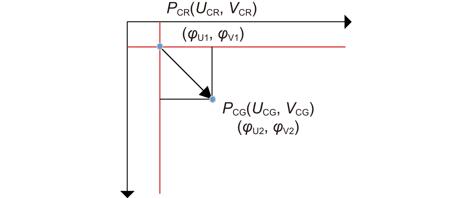
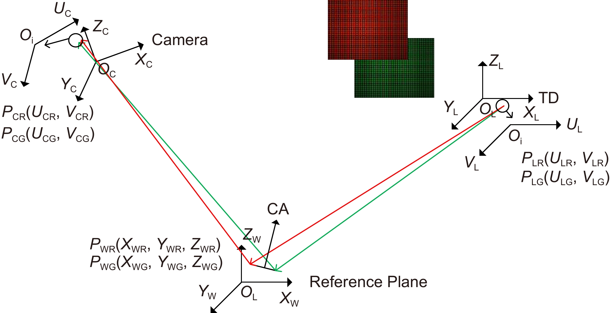
Figure 1.
Color difference schematic of the composite measurement system
-
Figure 2.
Pixel deviation map in the camera coordinate system
-
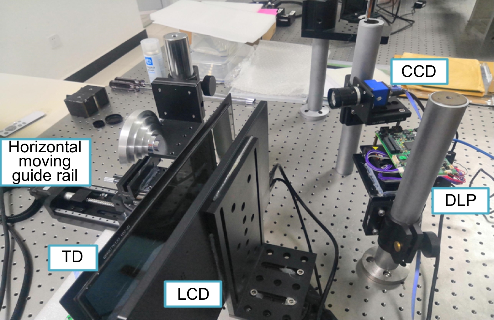
Figure 3.
Photo of the experimental system
-
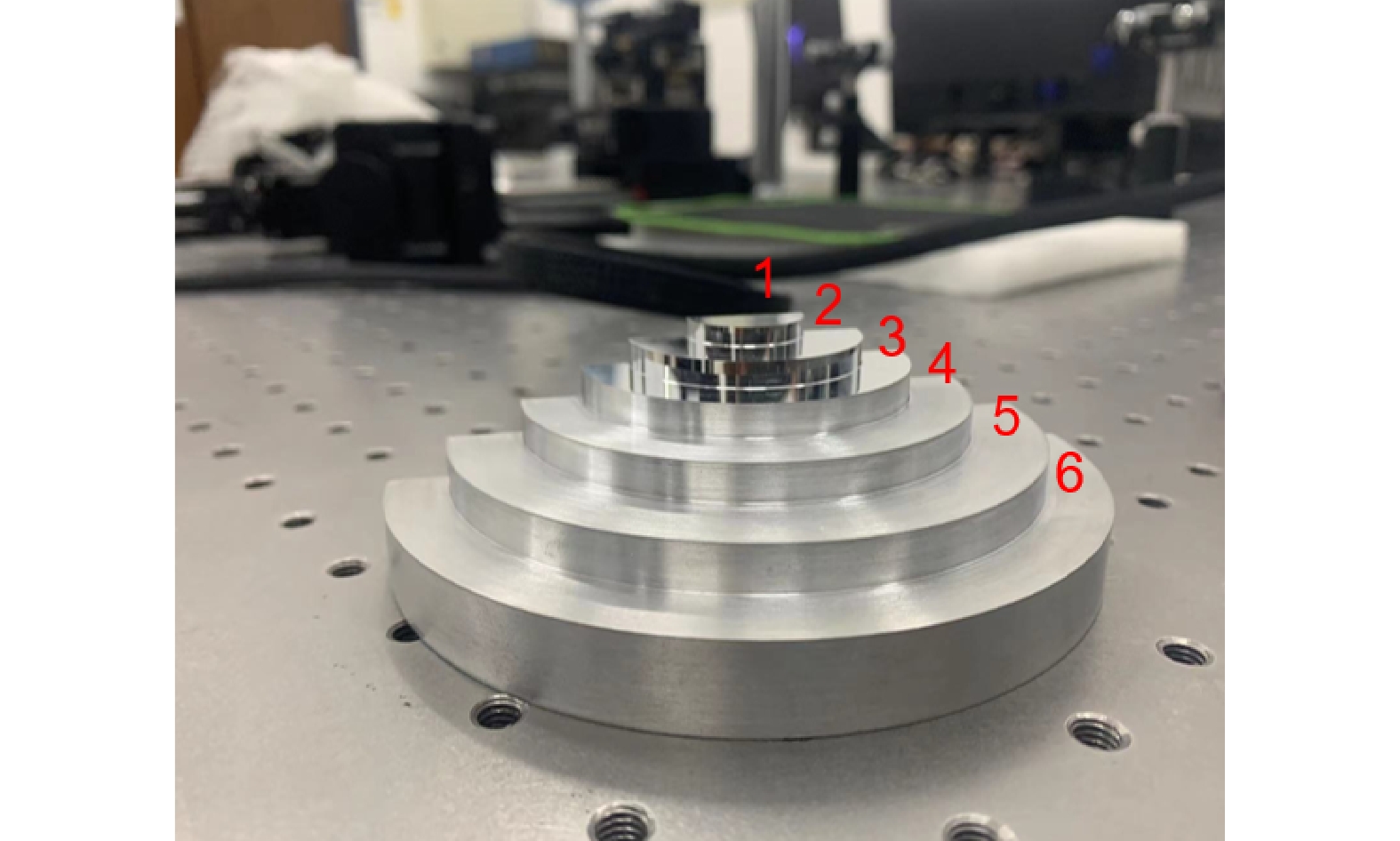
Figure 4.
Photo of the artificial composite step
-
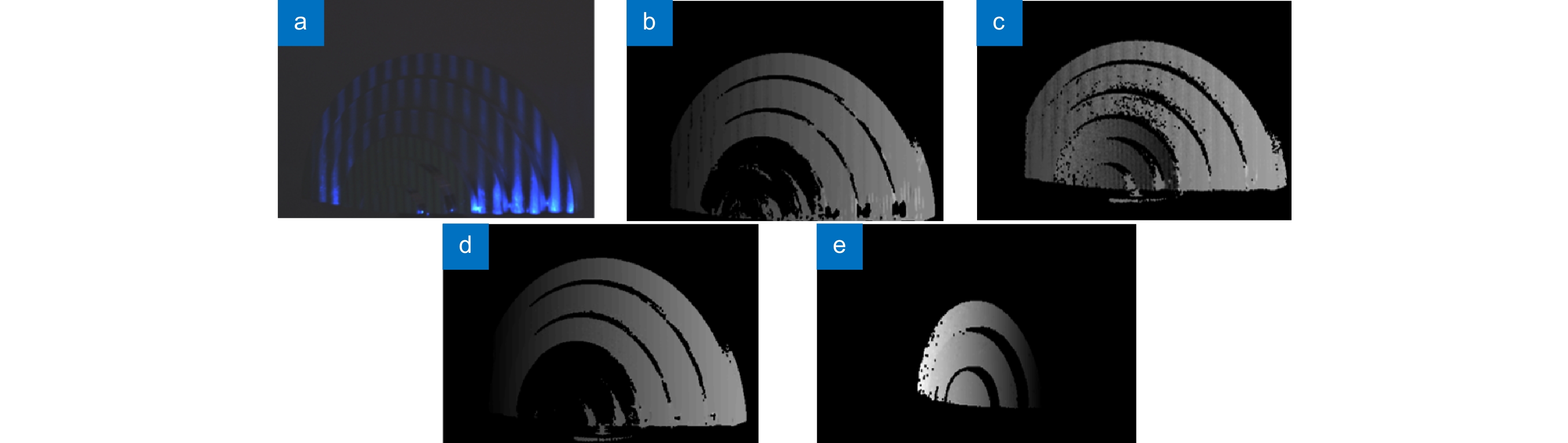
Figure 5.
Absolute phase diagram before and after crosstalk elimination. (a) A fringe map taken at the same time; (b) Absolute phase map of the blue channel before processing; (c) Absolute phase diagram of the green channel before processing; (d) Absolute phase diagram of the processed blue channel; (e) Absolute phase diagram of the processed green channel
-
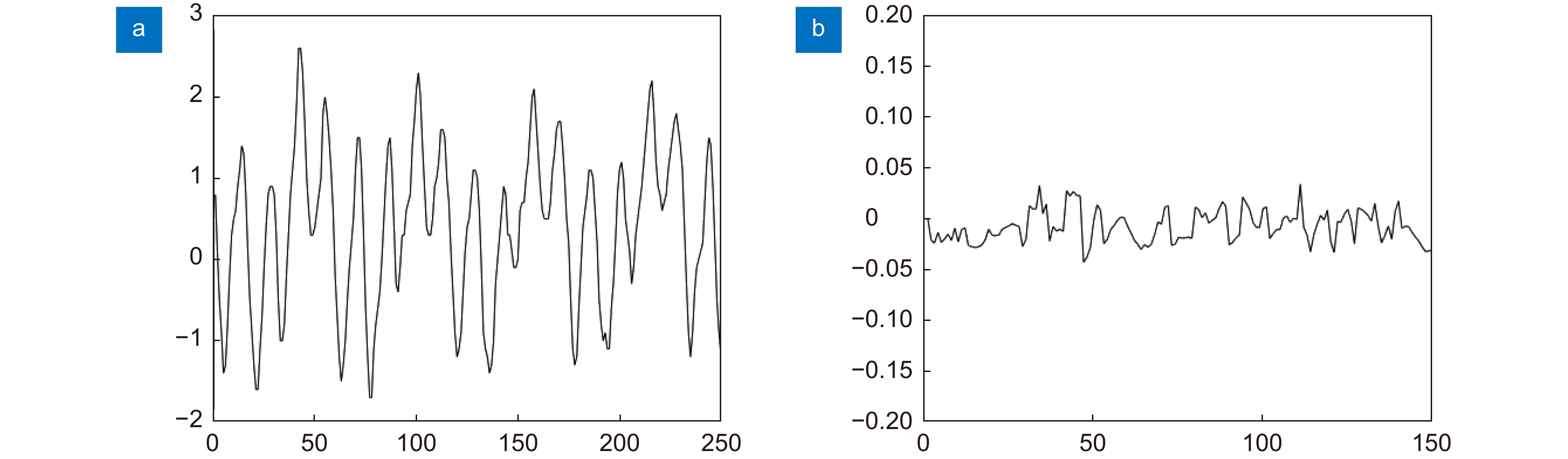
Figure 6.
Image of pixel deviation before and after color correction by the traditional method. (a) Image of pixel deviation before chromatic correction; (b) Image of pixel deviation after chromatic aberration correction
-
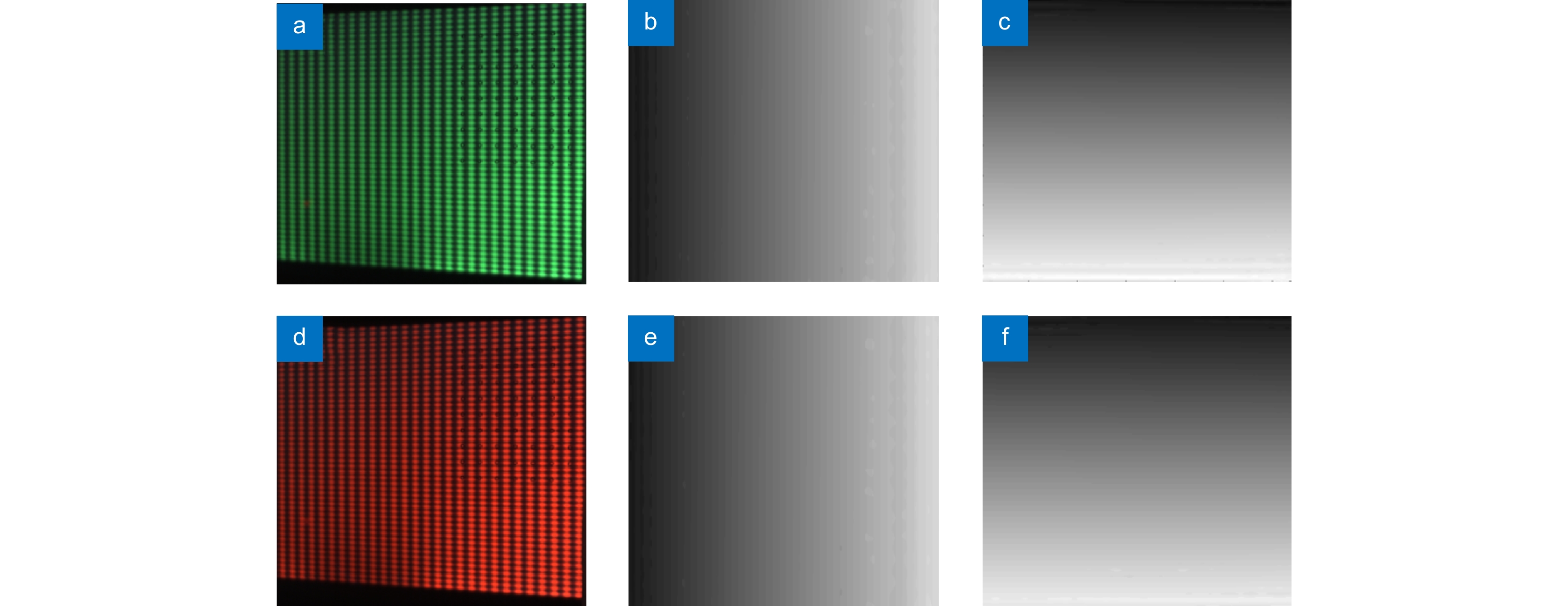
Figure 7.
Orthogonal fringe and unwrapping phase diagram. (a) Green orthogonal fringe pattern; (b) Vertical stripe unwrapping phase; (c) Horizontal fringe unwrapping phase; (d) Red orthogonal stripe pattern; (e) Vertical stripe unwrapping phase; (f) Horizontal fringe unwrapping phase
-
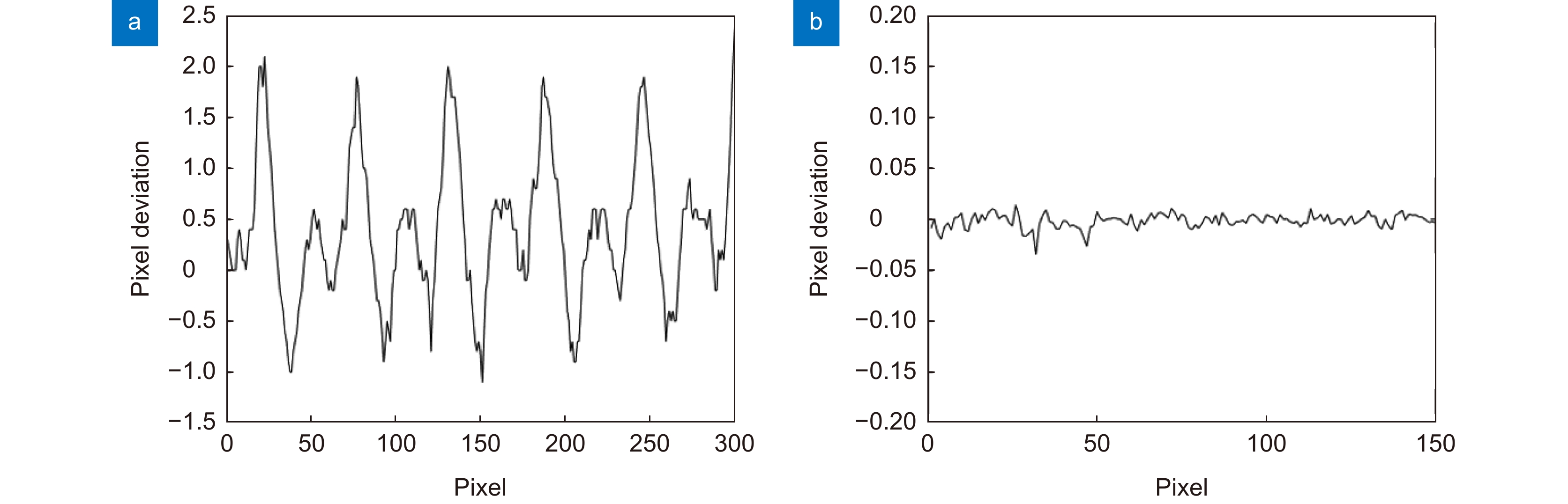
Figure 8.
Image of pixel deviation before and after chromatic aberration correction. (a) Image of pixel deviation before chromatic correction; (b) Image of pixel deviation after chromatic aberration correction
-
Figure 9.
Reconstructed depth map. (a) Depth map before error correction; (b) Error corrected depth map
-
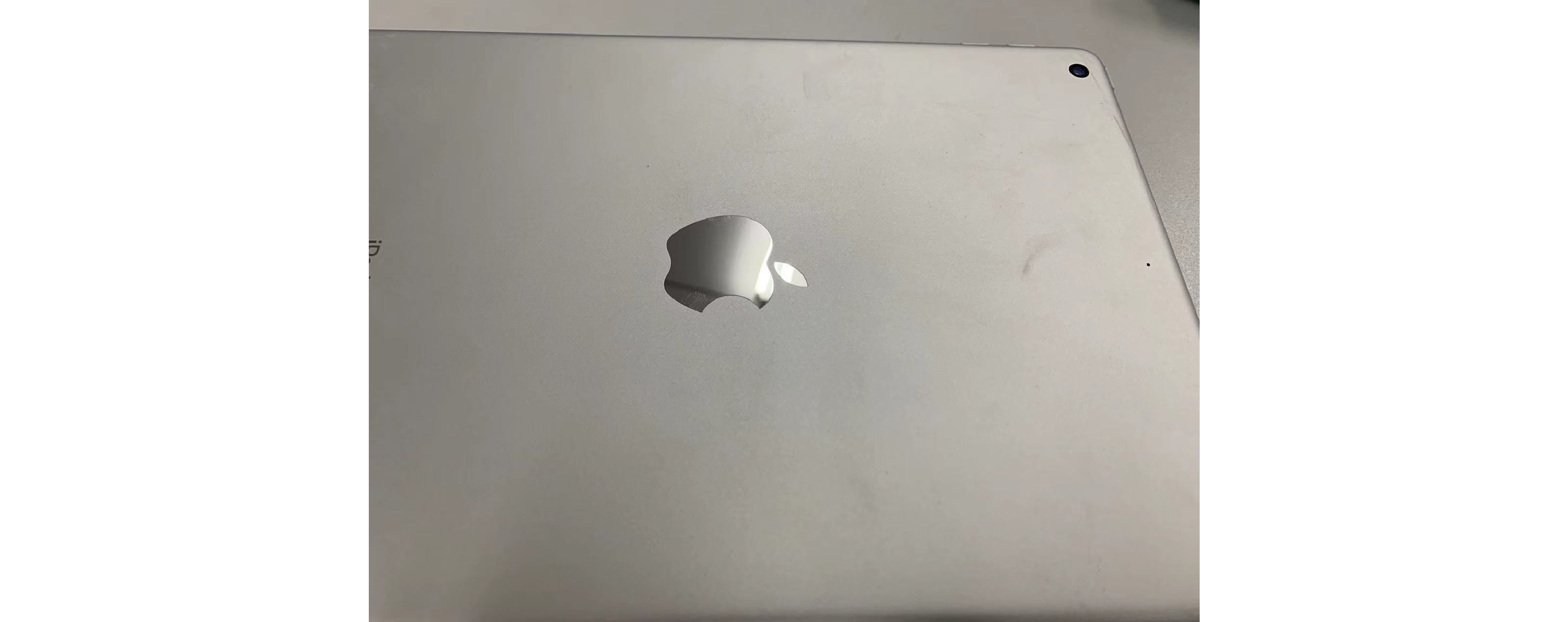
Figure 10.
Logo figure of iPad
-
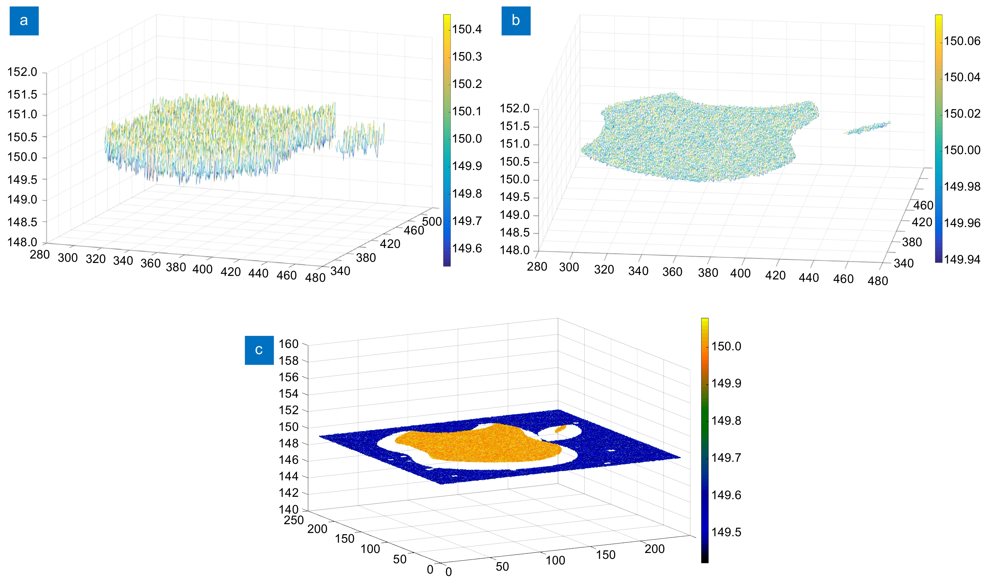
Figure 11.
Reconstructed depth map. (a) Mirror depth map before error processing; (b) Mirror depth map after error processing; (c) iPad logo rebuild depth map
- Figure .


